 [/img]
SS Rectifier
15 posts
• Page 1 of 1
SS Rectifier
![]() by ecir38 » Mon Feb 11, 2008 5:31 pm
by ecir38 » Mon Feb 11, 2008 5:31 pm
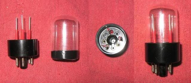
Thought ya'll would get a kick out of this. Here is a SS rectifier that I am preparing for my 300B G*S*G. Just need to solder some UF4007's across the leads now. If anyone is interesting in trying to make one I can give details on how I did this.
[/img]
[/img]-

ecir38 - Posts: 185
- Joined: Mon Nov 26, 2007 1:00 pm
- Location: New Orleans
Re: SS Rectifier
![]() by Slartibartfast » Mon Feb 11, 2008 6:05 pm
by Slartibartfast » Mon Feb 11, 2008 6:05 pm
ecir38 wrote:Thought ya'll would get a kick out of this. Here is a SS rectifier that I am preparing for my 300B G*S*G. Just need to solder some UF4007's across the leads now. If anyone is interesting in trying to make one I can give details on how I did this.
you need to add a some cool lookin neon glow, YO!
I would be interested in how you do this. I would like to do the same for the rectifier in my PAS.
-

Slartibartfast - KT88
- Posts: 458
- Joined: Sun Apr 15, 2007 9:40 pm
- Location: Columbia S.C.
![]() by EWBrown » Tue Feb 12, 2008 6:44 am
by EWBrown » Tue Feb 12, 2008 6:44 am
Interesting approach! For some "looks" you could add in a light across the filament connections either LEDs or incandescent (use a higher voltage bulb for that orange or yellow glow)
I've always had trouble removing the glass, without turning it into a million shards... :o
The simple / easy approach for a PAS is to take two UF4007s, connect the two cathodes together, and keep one of the cathode leadslong, then simply plug them directly into the tube socket, (the diode leads are about the same size / diameter as the 12X4 pins) with wo anodes where the plates connect, and the conjouned cathodes to the original cathode / B+ output connection. THis way, it's easily "reversible", and since it is hidden away under the top cover, appearance isn't a real factor.
/ed B in NH
Real Radios Glow in the Dark
-
EWBrown - Insulator & Iron Magnate
- Posts: 6389
- Joined: Wed Mar 19, 2003 6:03 am
- Location: Now located in Clay County, NC !
![]() by Slartibartfast » Tue Feb 12, 2008 7:23 am
by Slartibartfast » Tue Feb 12, 2008 7:23 am
EWBrown wrote:
The simple / easy approach for a PAS is to take two UF4007s, connect the two cathodes together, and keep one of the cathode leadslong, then simply plug them directly into the tube socket, (the diode leads are about the same size / diameter as the 12X4 pins) with wo anodes where the plates connect, and the conjouned cathodes to the original cathode / B+ output connection. THis way, it's easily "reversible", and since it is hidden away under the top cover, appearance isn't a real factor.
/ed B in NH
Thanks Ed,
Anything to lighten the load on the undersized PT. I have already removed the indicator bulb.
-
Slartibartfast - KT88
- Posts: 458
- Joined: Sun Apr 15, 2007 9:40 pm
- Location: Columbia S.C.
![]() by EWBrown » Tue Feb 12, 2008 7:30 am
by EWBrown » Tue Feb 12, 2008 7:30 am
THose little PA211s were seriously underbuilt... removing the 12X4 filament load and the 150 mA pilot light (which can be replaced with an LED and resistor, best to feed it from the DC side of the circuit) will remove around 30% of unnecessary current loading on the filament winding.
The rectifier "light" could be a couple of orange or amber LEDs connected back to back, with a suitable dropping resistor, they'll be OK with AC through them - but white, blue, UV and "true green" LEDs don't like too much "reverse" voltage - and keep the current fairly low, around 10 mA is more than enough, so something between 390 and 470 ohms, 1/4 watt, should be good.
/ed B in NH
Real Radios Glow in the Dark
-
EWBrown - Insulator & Iron Magnate
- Posts: 6389
- Joined: Wed Mar 19, 2003 6:03 am
- Location: Now located in Clay County, NC !
![]() by ecir38 » Tue Feb 12, 2008 11:27 am
by ecir38 » Tue Feb 12, 2008 11:27 am
I was inspired to make this after seeing that video that was floating around awhile back of that guy showing how to make a triode from scratch. I noticed a few things in that video that gave me this idea.
First this was not accomplished on my first attempt. After two attempts of some bad tubes I had I knew I could pull it off. The 6AX5 that this will be replacing are cheap enough so I bought a lot of 5 for 12 bucks with shipping on eBay. I only have one tube left that was the best of the lot LOL. Saying this hopefully you have some bad tubes lying around with the same pinout you will need.
For the first two tubes I tried, I broke the glass then cleaned out the socket and the other I grinded the bottom of the socket to remove the glass. So this took two tubes to get one piece of glass to work with. I scribed around the tube with a glass cutter that I had that wasn’t that sharp, when I tapped on the glass to try and separate it after scribing I got a small run on the piece that I needed. You need a clean cut without any runs to have a piece that will work. I used this now scrap piece to play with heating the glass up to get a feel for the right temperature to apply for when I had a piece that was workable. What you want to do is apply heat with a propane torch on close to its highest setting to the edge that was cut to reglaze and cleanup the cut. I have found that as soon as you see the edge glow red is all that is needed to clean it up. This makes the tube more durable when handling in the future.
For the lot of tubes I bought I was lucky to find one that was a little loose in its socket. If you have one like this to work with it is fairly easy to remove the glass from the socket by just twisting back and forth to break the leads that connect the tube to the socket. Unfortunately I had a run in the glass on this attempt too but now have two good sockets.
The next tube I grinded the bottom of the socket to break the glass away from the socket as described above. This time instead of using a glass cutter I used a small precision triangle file to scribe around the glass. I used a piece of blue painters tape as a guide at the longest straight section of the tube to run the file around the tube. The first one I tried this with I cut through too quick and had a small run. Take caution to apply an evenly scribed mark around the tube until you feel it almost through, this takes several rotations. I used a mouse pad to work off of. When you get to the right point the glass should just snap apart. You will here the cut running as you get close. To finish the glass apply heat as described above to reglaze the cut. I used black electrical tape to fit the tube in the socket tight. Some tubes are not this loose and will not need any tape.
Here is what I did to solder the wire to the pins. First off you will need to remove the existing wire from the pins. These are soldered at the through hole at the bottom of the pin. I used a micro torch to heat this up then pulled the wire out. Heat the pin up again with the torch and fill the pin with solder. While the solder is still hot insert your lead then allow to it cool. Now you have something to work with. The wire I like to use is scrap pieces from lighting ballasts, it is solid core and tin coated. I’m sure you can use what you normally use for hookup wire, I just wanted something stiff to work with.
Good Luck
-
ecir38 - Posts: 185
- Joined: Mon Nov 26, 2007 1:00 pm
- Location: New Orleans
![]() by EWBrown » Tue Feb 12, 2008 1:07 pm
by EWBrown » Tue Feb 12, 2008 1:07 pm
Another trick to cut the glass, is to use a length of nichrome wire (it can be taken from a broken toaster) and wrap a non-shorting ring around the tube glass where you want to cut it. I'd use an old "train" transformer, but a hefty 12-24VAC trannie and variac will also do the trick. Heat up the wire to yellow-hot, wait a few seconds, quickly pull out the glass and plunge it into cool water.
This should crack (internal stress crack, but enough to make the break) the glass where the hot wire was located.
I have a huge stash of "plinkers" so I have lots of expendable glass to experiment with.
One of the glass cutter wheel thingies might also work, but I can envision a lot of crushed tubes before the right "feel" and touch is figured out...
/ed B in NH
Real Radios Glow in the Dark
-
EWBrown - Insulator & Iron Magnate
- Posts: 6389
- Joined: Wed Mar 19, 2003 6:03 am
- Location: Now located in Clay County, NC !
![]() by ecir38 » Tue Feb 12, 2008 2:32 pm
by ecir38 » Tue Feb 12, 2008 2:32 pm
I tried the wire with a variac once with no luck. The hardest part trying to do this was keeping the wire tight enough around the tube when heat was applied. One part of the video I referenced above showed a tool made specifically for this.
I have to say though that the way I scribed the tube with the file took only two attempts to get it.
I have to say though that the way I scribed the tube with the file took only two attempts to get it.
-
ecir38 - Posts: 185
- Joined: Mon Nov 26, 2007 1:00 pm
- Location: New Orleans
![]() by ecir38 » Sun Feb 17, 2008 12:27 pm
by ecir38 » Sun Feb 17, 2008 12:27 pm
ed, I pulled this quote that you replied to me in this thread. http://www.diytube.com/phpBB2/viewtopic ... 3&start=30
Here is a schematic I put together.
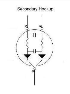
Does this look right for what you are describing above?
Would a RRFSR with the 0.001 uF 1600V disk ceramic caps be similiar to using a inrush current limiter like the CL-90?
Wondering also for those that have bought a Weber copper cap if they have taken one apart to see how he has them wired. http://www.webervst.com/ccap.html
EWBrown wrote:There is another approach, though I've not tested it, connect a 10 ohm 5W WW resistor in series between each "hot" lead of the power trannie's HV secondary and its associated diode rectifier, and then connect one 0.001 uF, 1600V (or greater) disk ceramic cap across the secondary, and a second similar cap between the two diodes' anodes. This results in what is known as a rapid reverse spike recovery filter (RRFSR) , and should work.
The simple version of this is to connect the 0.001 uF 1600V disk ceramic caps across each rectifier diode. Not as effective, it is "old school" approach.
/ed B in NH
Here is a schematic I put together.
Does this look right for what you are describing above?
Would a RRFSR with the 0.001 uF 1600V disk ceramic caps be similiar to using a inrush current limiter like the CL-90?
Wondering also for those that have bought a Weber copper cap if they have taken one apart to see how he has them wired. http://www.webervst.com/ccap.html
-
ecir38 - Posts: 185
- Joined: Mon Nov 26, 2007 1:00 pm
- Location: New Orleans
![]() by Slartibartfast » Sun Feb 17, 2008 1:05 pm
by Slartibartfast » Sun Feb 17, 2008 1:05 pm
ecir38 wrote:
Wondering also for those that have bought a Weber copper cap if they have taken one apart to see how he has them wired. http://www.webervst.com/ccap.html
Yes I have one and the answer is no. It does not look like it would go back together too easily. Add to that, the copper cover gets real hot. I think it is used as a heat sink. I do not how effective it would be, if it were disassembled.
-
Slartibartfast - KT88
- Posts: 458
- Joined: Sun Apr 15, 2007 9:40 pm
- Location: Columbia S.C.
![]() by EWBrown » Tue Feb 19, 2008 8:25 am
by EWBrown » Tue Feb 19, 2008 8:25 am
That looks about right, I "lifted" the idea from the Bottlehead site.
The whole purpose is to snub / absorb the reverse recovery spikes.
The 10 ohm resistors won't get too hot, as they have very little actual voltage drop thru them. Even 100 ohms (though the power rating must necessarily increase with these) would be OK and give that little bit of "droop" to more simulate a rectifier tube.s characteristics. Stick with 10 ohms for the glass "tube".
This doesn't substitute for the ICL CL-90, I'd still add one of them to the AC primary side, just for good measure. Not truly "mandatory", but just a little bit of added protection for the SS rectifier diodes.
/ed B in NH
Real Radios Glow in the Dark
-
EWBrown - Insulator & Iron Magnate
- Posts: 6389
- Joined: Wed Mar 19, 2003 6:03 am
- Location: Now located in Clay County, NC !
![]() by nyazzip » Wed Feb 20, 2008 12:34 am
by nyazzip » Wed Feb 20, 2008 12:34 am
i wonder if Dremel makes cutoff wheels that will do glass? seems like a carbide impregnated wheel would do a nice job. maybe they just don't make cutoff wheels with that level of hardness.
...not being a safety nut, this is still one job i'd certainly use goggles for...dremel-on-tube= powdered glass....yikes
...not being a safety nut, this is still one job i'd certainly use goggles for...dremel-on-tube= powdered glass....yikes
-

nyazzip - KT88
- Posts: 1073
- Joined: Wed Jan 09, 2008 1:24 am
![]() by ecir38 » Wed Feb 20, 2008 11:04 am
by ecir38 » Wed Feb 20, 2008 11:04 am
If you have some bad tubes to play with I guess it would be worth a shot. Don't see any need for a special bit, a regular stone should work.
I think the trick is to not cut through in just one spot. You want to evenly scribe around the whole tube so that when you get close to cutting through the whole piece it will just snap apart.
I think the trick is to not cut through in just one spot. You want to evenly scribe around the whole tube so that when you get close to cutting through the whole piece it will just snap apart.
-
ecir38 - Posts: 185
- Joined: Mon Nov 26, 2007 1:00 pm
- Location: New Orleans
![]() by ecir38 » Mon Mar 17, 2008 5:38 pm
by ecir38 » Mon Mar 17, 2008 5:38 pm
A few pics of one I built with a ST type tube.
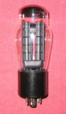
note led's at top
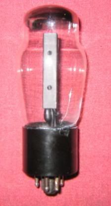
I have a run on the back side. Willl try again after I find some more cheap tubes to play with.
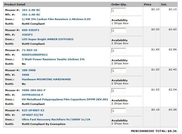
Parts used from Mouser.
I used mounting hardware in BOM above to hide wires for led and to kinda resemble an actual tube.
note led's at top
I have a run on the back side. Willl try again after I find some more cheap tubes to play with.
Parts used from Mouser.
I used mounting hardware in BOM above to hide wires for led and to kinda resemble an actual tube.
-
ecir38 - Posts: 185
- Joined: Mon Nov 26, 2007 1:00 pm
- Location: New Orleans
15 posts
• Page 1 of 1
Who is online
Users browsing this forum: No registered users and 51 guests