I wonder why Dynaco oriented the coupling caps one way in the Stereo 70 and the other way in the Mark III?
In the original samples I have, which correspond to the images on the covers of the respective manuals, the coupling caps on the Stereo 70 PCB have the outer foil looking toward the 7199. But, the Mark III coupling caps' outer foil is looking toward the KT88s.
Dynaco PCBs were always factory assembled, so the capacitors in question were not oriented by the kit builder. Assuming Dynaco made most or all of the PC boards this way, can anyone think of any differences in the Mark III vs. the Stereo 70 that would account for this?
Thanks.
Peter
Outer foil: Mark III vs. Stereo 70
10 posts
• Page 1 of 1
Outer foil: Mark III vs. Stereo 70
![]() by petercapo » Wed Dec 19, 2012 11:13 pm
by petercapo » Wed Dec 19, 2012 11:13 pm
Last edited by petercapo on Thu Dec 20, 2012 3:02 am, edited 1 time in total.
- petercapo
- Posts: 36
- Joined: Fri May 28, 2010 11:51 am
Re: Outer foil: Mark III vs. Stereo 70
![]() by Geek » Wed Dec 19, 2012 11:23 pm
by Geek » Wed Dec 19, 2012 11:23 pm
Because non-polarized cap hoodoovoodoo didn't exist back then? 
-= Gregg =-
Fine wine comes in glass bottles, not plastic sacks. Therefore the finer electrons are also found in glass bottles.
Fine wine comes in glass bottles, not plastic sacks. Therefore the finer electrons are also found in glass bottles.
-
Geek - KT88
- Posts: 3585
- Joined: Sun Oct 21, 2007 3:01 am
- Location: Chilliwack, British Columbia
Re: Outer foil: Mark III vs. Stereo 70
![]() by petercapo » Wed Dec 19, 2012 11:27 pm
by petercapo » Wed Dec 19, 2012 11:27 pm
Even in those days, capacitor manufacturers marked the outer foil, usually with a band around one end, as you probably know. I am not sure I could believe they went to the trouble for no reason. And, by the way, I am not attempting to introduce any form of discussion about the merits, or lack thereof, of "boutique" parts. Fifty years ago, garden variety capacitors like those in the Stereo 70 and Mark III had the outer foil marked.
So, are you trying to say it was a consistent accident that the outer foil went one way in the Stereo 70 and the other way in the Mark III?
So, are you trying to say it was a consistent accident that the outer foil went one way in the Stereo 70 and the other way in the Mark III?
Last edited by petercapo on Sat Dec 22, 2012 6:00 pm, edited 2 times in total.
- petercapo
- Posts: 36
- Joined: Fri May 28, 2010 11:51 am
Re: Outer foil: Mark III vs. Stereo 70
![]() by Geek » Thu Dec 20, 2012 12:04 am
by Geek » Thu Dec 20, 2012 12:04 am
Outer foil is important when it comes to one end being at ground potential (bypassing) or pointing towards the lowest impedance source (modern drivers), but as for general coupling, I have found no improvement either way.
Cheers!
Cheers!
-= Gregg =-
Fine wine comes in glass bottles, not plastic sacks. Therefore the finer electrons are also found in glass bottles.
Fine wine comes in glass bottles, not plastic sacks. Therefore the finer electrons are also found in glass bottles.
-
Geek - KT88
- Posts: 3585
- Joined: Sun Oct 21, 2007 3:01 am
- Location: Chilliwack, British Columbia
Re: Outer foil: Mark III vs. Stereo 70
![]() by Shannon Parks » Sat Dec 22, 2012 6:43 am
by Shannon Parks » Sat Dec 22, 2012 6:43 am
Interesting. So it seems to me that they'd always orient the band or outer foil towards the phase inverter, as that would always have a lower impedance than the grid resistor. Looking at an ST70 and MKIV driver here, indeed that's how they were built. Unfortunately I don't have a MKIII driver - anyone want to check theirs to compare with Peters?
Wait a sec - my ST70 screen bypass caps are flip-flopped. So what does that tell you?
Shannon
Wait a sec - my ST70 screen bypass caps are flip-flopped. So what does that tell you?
Shannon
- designer of fine tube audio gear at (((parks audio)))
- founder and admin of the diytube forums
-

Shannon Parks - Site Admin
- Posts: 3764
- Joined: Tue Mar 18, 2003 5:40 pm
- Location: Poulsbo, Washington
Re: Outer foil: Mark III vs. Stereo 70
![]() by Ty_Bower » Sat Dec 22, 2012 6:55 am
by Ty_Bower » Sat Dec 22, 2012 6:55 am
I sold off the original driver boards from my Mark III. That was years ago, but I did keep a few photos around. Here they are:
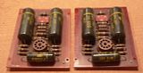
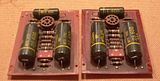
If they build anything the way I do, usually components are stuffed so all the text (or other printed labeling, such as resistor color bands) are aligned in an esthetically pleasing orientation.


If they build anything the way I do, usually components are stuffed so all the text (or other printed labeling, such as resistor color bands) are aligned in an esthetically pleasing orientation.
"It's a different experience; the noise occlusion, crisp, clear sound, and defined powerful bass. Strong bass does not corrupt the higher frequencies, giving a very different overall feel of the sound, one that is, in my opinion, quite unique."
-
Ty_Bower - KT88
- Posts: 1494
- Joined: Wed Mar 21, 2007 2:50 pm
- Location: Newark, DE
Re: Outer foil: Mark III vs. Stereo 70
![]() by petercapo » Sat Dec 22, 2012 1:23 pm
by petercapo » Sat Dec 22, 2012 1:23 pm
Shannon,
I believe you are referring to the 0.05uf caps on the Stereo 70 PCB? "Flip-flopped" in what way, please? The left half of the Stereo 70 PCB is physically a mirror-image of the right half. Because the 0.05uf caps are mounted along the shorter axis of the PCB, it is unavoidable that the band printed on the body of each one would appear flip-flopped relative to each other on the top of the board while their respective outer foil ends are nevertheless connected to the very same corresponding point in each channel’s circuit. I have confirmed this by tracing the circuit side. But, perhaps you meant something else by "flip-flopped?"
With regard to the Mark III's aesthetics, if it were purely an aesthetics consideration, I would think that the bands on both of the large coupling caps would face the same way as each other only, and randomly with regard to either end of the board. In other words, I am not sure that, aesthetically, it would make much difference on the top side if these caps (together) faced toward one end of the PCB or if they faced the other end, if you see what I am getting at. In spite of this, they do always seem to be facing the same way, at least in all the samples I have or have seen images of.
With regard to the Mark III circuit, the outer foil of those caps seems to always be facing in the direction of the KT88s. I am wondering if Dynaco possibly did a test and found the noise level was lower one way in the Mk. III, and the other way in the ST-70?
Of course, we’ll never know what Dynaco had in mind, if anything. But, I thought it might be interesting to discuss.
Thanks.
Peter
- petercapo
- Posts: 36
- Joined: Fri May 28, 2010 11:51 am
Re: Outer foil: Mark III vs. Stereo 70
![]() by Ty_Bower » Sun Dec 23, 2012 8:02 am
by Ty_Bower » Sun Dec 23, 2012 8:02 am
petercapo wrote:Dynaco PCBs were always factory assembled... the capacitors in question were not oriented by the kit builder.
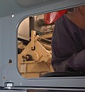
Although they may have been assembled by the factory, I assume they were stuffed (and probably soldered) by hand. I have an image of something like this except capacitors, not ammunition cartridges:

They probably had an instruction card for the workers to follow at each station. The person stuffing the caps just matched the part on hand with the image on the instruction card. When the instruction card was printed, the orientation was essentially random. The image on the card was probably the same one that ended up in the Owner's manuals as well. After that, the thousands of factory assembled circuit boards were all just clones of the picture.
"It's a different experience; the noise occlusion, crisp, clear sound, and defined powerful bass. Strong bass does not corrupt the higher frequencies, giving a very different overall feel of the sound, one that is, in my opinion, quite unique."
-
Ty_Bower - KT88
- Posts: 1494
- Joined: Wed Mar 21, 2007 2:50 pm
- Location: Newark, DE
Re: Outer foil: Mark III vs. Stereo 70
![]() by Shannon Parks » Sun Dec 23, 2012 12:54 pm
by Shannon Parks » Sun Dec 23, 2012 12:54 pm
petercapo wrote: I have confirmed this by tracing the circuit side. But, perhaps you meant something else by "flip-flopped?"
Peter, you are correct. The bands are not symmetrical on the board, but the banded end of the .05uF bypass cap does indeed go to the cathode on both sides. So the banded end of all six caps on the ST70 board go to the lower impedance connection.
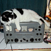
Here's the original "in situ" photo of the driver (rescued from a gator poacher in the Everglades):
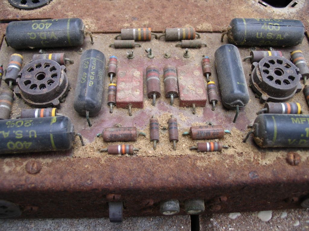
Shannon
- designer of fine tube audio gear at (((parks audio)))
- founder and admin of the diytube forums
-
Shannon Parks - Site Admin
- Posts: 3764
- Joined: Tue Mar 18, 2003 5:40 pm
- Location: Poulsbo, Washington
10 posts
• Page 1 of 1
Who is online
Users browsing this forum: No registered users and 14 guests