Hi all, I am a new member amd am building a pair of Mk III clones with the transformers from Triode, purchased the driver board from them too. I searched and can't find anyone that has asked this question so apologize if this is a "known fact".
On the schematic I note that C4/R12 connect to point G and C5/R13 connect to point F however looking at the board its backwards with C4/R12 to F - which is right? Obviously the board is etched and labled but would not the phase of the output transformer be backwards? And should G go to the blue & green side instead of F?
Simple enough to swap and don't think it would actually damage anything but this has me puzzled so I thought I would ask.
Thanks All - Dave
PC Board Question
5 posts
• Page 1 of 1
PC Board Question
![]() by n8zfm » Tue Apr 05, 2011 5:14 pm
by n8zfm » Tue Apr 05, 2011 5:14 pm
- n8zfm
- Posts: 4
- Joined: Wed Mar 30, 2011 6:15 pm
- Location: Louisville
![]() by Shannon Parks » Tue Apr 05, 2011 6:18 pm
by Shannon Parks » Tue Apr 05, 2011 6:18 pm
Nice catch! Follow the hook-up (F & G to the colors listed) from the schematic, Dave. I'll try and fix the schematic for the component numbering. Good luck with your build.
Shannon
Shannon
-

Shannon Parks - Site Admin
- Posts: 3764
- Joined: Tue Mar 18, 2003 5:40 pm
- Location: Poulsbo, Washington
![]() by Ty_Bower » Tue Apr 05, 2011 7:28 pm
by Ty_Bower » Tue Apr 05, 2011 7:28 pm
F goes to the solid blue and green side. G goes to the striped side.

"It's a different experience; the noise occlusion, crisp, clear sound, and defined powerful bass. Strong bass does not corrupt the higher frequencies, giving a very different overall feel of the sound, one that is, in my opinion, quite unique."
-

Ty_Bower - KT88
- Posts: 1494
- Joined: Wed Mar 21, 2007 2:50 pm
- Location: Newark, DE
I understand now.... and one more pesky question
![]() by n8zfm » Tue Apr 05, 2011 9:04 pm
by n8zfm » Tue Apr 05, 2011 9:04 pm
Thank you Shannon, I now have it figured out, the slik screen F and G are correct, its the silkscreen part numbers for C4/C5 and the associated resistors that are flipped, I followed the trace from the V2 PIN and the light came on. I did not look at the input to C4/C5 to see which pin the trace there was going to. Funny - If I was just soldering the parts on they are symertical so it makes no difference in practice.
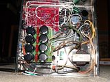
I will send along a picture once I get the 1st one finished, I added a softstart for the filaments and PC boarded the bias supply, I have used a simple softstart with expensive transmitting tubes just so as not to shock the cold filaments, not sure its necessary here but what the heck, diode, 2 48v relays and a couple caps, 2 resistors.
My question -
I plan on using and have panel mount trimmers for both balance and bias voltage (I know this is not really needed) parts Mouser 652-3006P-1-504-LF and 652-3006P-1-103-LF with a panel mount adaptor 652-H83P they are both 3/4W units, is this enough dissapation for the 10K? I actually have no idea how to calculate the current in the negative bias supply. I am a hobbyist and make my living as a systems engineer in IT.
Thanks,
Dave
- n8zfm
- Posts: 4
- Joined: Wed Mar 30, 2011 6:15 pm
- Location: Louisville
![]() by dcgillespie » Tue Apr 05, 2011 9:58 pm
by dcgillespie » Tue Apr 05, 2011 9:58 pm
Dave -- A 3/4 watt rating is more than enough, since the 10K pot actually dissipates something less than .1 watt in reality.
Good luck with your projects!
Dave
Good luck with your projects!
Dave
- dcgillespie
- KT88
- Posts: 399
- Joined: Sun Mar 08, 2009 5:34 am
- Location: Ball Ground, GA
5 posts
• Page 1 of 1
Who is online
Users browsing this forum: No registered users and 21 guests