Weekend SE 6GK6 project - and PSE 6DZ7s

the thermionic watercooler

Weekend SE 6GK6 project - and PSE 6DZ7s

Postby EWBrown » Mon Aug 16, 2010 1:49 pm

What to do with two 6GK6s, two 6CG7s, two Edcor GXSE10-8-5Ks, a Hammond 272BX power trannie and 10X6X2 chassis, and a handful of small components... Bad knee keeping me kinda down, so rather than enjoying the nice summer weather outside, I decided to cobble this little puppy up, designing and building it "on the fly"... No NFB, naturally. O:)

Image

Image

Image

SRPP 6CG7 drivers, SE UL 6GK6s, and a surprisingly very good sounding amplifier resulted. Started Saturday afternoon, just finished it this morning (Aug 16, 2010) It's been playing about 5 hours, and the sound is really growing on me [:) :))

The 272BX developed too high a B+ voltage (nearly 400VDC, so I used the otherwise unemployed 5V filament winding to buck the AC line voltage back to 115VAC, and the B+ came out at 380VDC, right where I wanted it.
I'm running the 6GK6s at 40 mA cathode current, this seems to fall right into the sweet spot, even though it's pushing the PD ratings a bit beyond the edge. In teh spirit of Tube Lab George, if the late isn't glowing cherry red, it isn't working hard enough ;) (666) So, I just pushed the edge of the envelope just a little, this time around.

/ed B
Last edited by EWBrown on Tue Nov 08, 2011 8:04 pm, edited 3 times in total.
Real Radios Glow in the Dark
User avatar
EWBrown
Insulator & Iron Magnate
 
Posts: 6389
Joined: Wed Mar 19, 2003 6:03 am
Location: Now located in Clay County, NC !

Postby Geek » Mon Aug 16, 2010 3:12 pm

Awesome!

6GK6 == 6BQ5 with different pinout, so it'll sounnd good and take abuse ;)

Cheers!
-= Gregg =-
Fine wine comes in glass bottles, not plastic sacks. Therefore the finer electrons are also found in glass bottles.
User avatar
Geek
KT88
 
Posts: 3585
Joined: Sun Oct 21, 2007 3:01 am
Location: Chilliwack, British Columbia

Postby 20to20 » Mon Aug 16, 2010 4:47 pm

I decided to cobble this little puppy up


Puppy cobbler...Mmmm, Mmmm, looks delicious.
You're a peach of a cobbler EB..
Headed for Tishomingo to sing in a can...
User avatar
20to20
KT88
 
Posts: 566
Joined: Wed Apr 21, 2010 1:48 pm
Location: W-S, NC

Postby Ty_Bower » Mon Aug 16, 2010 8:10 pm

I like your work, Ed. Reminds me I need to learn how to wire stuff up point to point, instead of relying on circuit boards all the time.
"It's a different experience; the noise occlusion, crisp, clear sound, and defined powerful bass. Strong bass does not corrupt the higher frequencies, giving a very different overall feel of the sound, one that is, in my opinion, quite unique."
User avatar
Ty_Bower
KT88
 
Posts: 1494
Joined: Wed Mar 21, 2007 2:50 pm
Location: Newark, DE

Postby Geek » Mon Aug 16, 2010 8:57 pm

Ty_Bower wrote:I need to learn how to wire stuff up point to point, instead of relying on circuit boards all the time.


=:o :'(

Cheers!
-= Gregg =-
Fine wine comes in glass bottles, not plastic sacks. Therefore the finer electrons are also found in glass bottles.
User avatar
Geek
KT88
 
Posts: 3585
Joined: Sun Oct 21, 2007 3:01 am
Location: Chilliwack, British Columbia

Postby EWBrown » Tue Aug 17, 2010 3:52 pm

This one actually started out as (yet another) 6/13EM7 project, but then I saw that quad of 6GK6s just sitting around looking lonesome and forlorn , and I've got loads of used but good 6CG7s and 8CG7s, so rather than simply cloning a clone of another amp, I decided to break some new ground (and a wee bit of wind, too) ;) (lol) O:)

I've been carrying this 6CG7 / 6GK6 design around in my mind, for over a year, so I decided to committ it to metal and glass, rather than just mental vaporware and paper.

Rev 2 is already on the drawing board, this time, with PSET-UL and using GXSE15-8-3.5K OPTs, for MORE POWER !!!!!! (666) :)) (lol)

I'll probably use some 16GK6s (Have lots of them) and a very compact Sony Viao 16VDC SMPS "brick" to light them up. These work well, I modded one of my 16A8 modded K502s with a similar SMPS for the filaments. Got rid of a nagging hummmm problem (due to the poor PCB layout).

Another nice thing about using 16VDC filaments, is that the drivers can be 8CG7s or 8GU7s, filaments wired in series. Go for the "plinkertron" design ;)

The SRPP is my "standard" design, RK and RA = 1K, 1%, 1/2 W, and 220 ohm carbon comp grid stoppers on both grids. This is very flexible and allows for any of the more popular twin triodes in the 9A or 9AJ pinout.

The latest 300B SET uses the exact same circuit, except built on an AES turret board. Its 5965s consume about 3.2 mA each, and they are decoupled from the main B+ supply through a CRCRC filter.

The 6CG7s draw a tad over 5 mA each with a B+ of 340VDC, which is dropped from the main 380VDC B+ through a 3.9K, 3W resistor (leftover from the Aikido AIO supplied parts). 6CG7s are a perfect match for driving the 6GK6s, just the right amount of gain to do the job. 6GU7s would also work very well, and are drop-in interchangeable. 6GU7s would consume around 6.5 mA each.

This SRPP design is simple enough so that it can be done P2P very easily and neatly.

/ed B
Last edited by EWBrown on Mon Feb 14, 2011 7:28 pm, edited 1 time in total.
Real Radios Glow in the Dark
User avatar
EWBrown
Insulator & Iron Magnate
 
Posts: 6389
Joined: Wed Mar 19, 2003 6:03 am
Location: Now located in Clay County, NC !

Mid-Week Project

Postby EWBrown » Fri Aug 20, 2010 9:45 am

I was digging through the tube stash and could find only three more reasonably closely matched 6GK6s, and the 16GK6 situation is also three assorted brands of NOS and the reat are all used, tested, and "all over the map" as far as transconductance.

And I found that I had a some NOS RCA and GE 6DZ7s just pining away, so I changed course, and built up a 6DZ7 UL PSET during Wednesday and Thursday. FWIW< the RCAs have the GE marking codes, so I'd say these are ALL of GE manufacture.

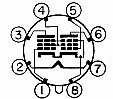
6DZ7s are essentially two 6BQ5s (or 6GK6s) packaged in an octal "fat bulb" envelope. Cathodes and screen grids are shared on their own pins, otherwise it would have to be at least a 10 pin base =:o

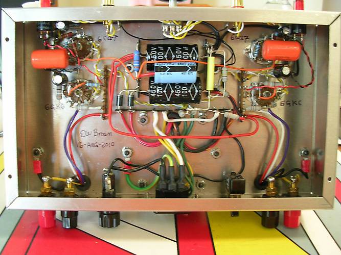
There is one slight difference with 6DZ7s, they like to have a lower G1 grid resistor than do individual or palallel 6BQ5s, so I ended up using 110K ohms (actually two 220K resistors parallel) , and 0.68 uF Auricap interstage coupling caps.

With 220K grid resistor, the G1 voltage was a bit unstable, and adding the second 220K in parallel neatly cured that issue. I refered again to the 6DZ7 data sheets, and it states that the maximum grid resistor value is 300K per section, so 150K should work, I went with 110K because it was easier to parallel a second 220K resistor than it would have been to search for, then swap in a 150K resistor (and remove the first 220K resistor) .

Just like lightning, I prefer the path of least resistance (lol) :))

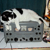
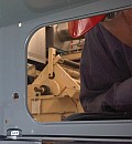
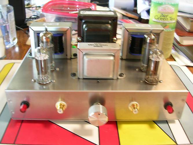
If all neatly fits on an old Bud 13 X 7X 2 chassis. Power trannie is a PA774 (naturally), and OPTS are GXSE15-9-5K. Driver is the same 6CG7 SRPP circuit which has become my "standard" for current and future designs. It looks very similar to the 6GK6 amp, just on a larger chassis needed to accomodate the larger power and output iron, and fatter tubes.

Sounds very good, is totally hum and ripple free (thanks to a total of over 700 uF of PSU filtering), and is more powerful than the previous 6GK6 UL SET amp. B+ is about 365VDC (same as in the ST35s) and each pentode section is drawing about 38 mA, slightly higher than the "normal" ST35 value. I use 200 ohm, 5W WW cathode resistors, bypassed with 470 uF / 50V which I had in my parts stash. I considered using GXSE15-8-3.5K OPTs for this project, for even more output power, but the THD would have been somewhat higher, and I have another planned purpose for these OPTs.

Photos to be posted soon.

I have some more NOS 6DZ7s, perhaps a simple, low-tube-count PP design is next... With the "compact amp" design, I could design a three-tube stereo PP amp [:) Or with SRPP drivers as in the "Odd Watt" design, four tubes (with 6CG7, 5965 or 12AT7 drivers).

Update: Now that it has about ten hours' of run time, the amp is starting to sound REALLY good, I s'pose that the coupling cap and OPTs really DO undergo a "break-in" process. [:)

/ed B
Last edited by EWBrown on Fri Aug 20, 2010 5:51 pm, edited 1 time in total.
Real Radios Glow in the Dark
User avatar
EWBrown
Insulator & Iron Magnate
 
Posts: 6389
Joined: Wed Mar 19, 2003 6:03 am
Location: Now located in Clay County, NC !

Postby TerrySmith » Fri Aug 20, 2010 11:17 am

Do you have a schematic? Looks like a really interesting circuit.

And of course I will keep the Plinkertron theme going with possibly 5965 / 12CG7 / 12AU7 for inputs and 29GK6 outputs.
T. Smith
User avatar
TerrySmith
KT88
 
Posts: 973
Joined: Sat Jan 31, 2004 12:51 pm
Location: Maryville TN

Postby 20to20 » Fri Aug 20, 2010 11:42 am

Ed,

Wonder what the channel seperation numbers are like for that if a single tube is used in stereo? One GE data sheet I found didn't specify. Perhaps it's not a great number...

and each pentode section is drawing about 38 mA,


How did you get the individual section currents, with a common cathode?

Thanks much!
Headed for Tishomingo to sing in a can...
User avatar
20to20
KT88
 
Posts: 566
Joined: Wed Apr 21, 2010 1:48 pm
Location: W-S, NC

Postby EWBrown » Fri Aug 20, 2010 5:39 pm

I'm making the somewhat rash presumption that both sections in an NOS 6DZ7 should be reasonably closely matched. :/

For the 6DZ7 connections, refer to this:

Image

The only difference is that I used grid stoppers for each G1.

(The original topic from which this image was taken was showing how a 6DZ7 pinout compares to that of a 6L6)

One way to be able to measure the individual section plate currents would be to connect a 10 ohm resistor in series with each plate. Then measure the voltage across the resistor, and multiply that voltage X 100 to determine the actual plate's current. Example: .380V would equate to 38 mA. (If you're using millivolts, then divide by 10)

To get the total current from both sections just measure across the cathode resistor, in this case 2X 38 mA is 76 mA, and that would measure as 15.2V across 200 ohms. The cathode voltage / current reading also takes in account the screen grid curent, which I measured as 1VDC across 100 ohms, as being very close to 10 mA.

I do have a "scribbled" schematic, just translating it to a form which can be displayed here will take a fairly prolonged process (I don't have a working scanner, and photographs of scribbles schematics are a poor method. I'll work something out... There are no secret circuit techniques, it is all "textbook" circuits. Just basic SRPP (1K RK and RA) and standard UL connections, with individual 220 ohm (can also be 1K) grid stoppers for each G1, plates (pins 3 and 6) connected together.

PSU is basically "stolen" from the DIY ST35 design , I used a PA774, two MUR4100E rectifiers (uF4007s or uF5408s are perfectly good here), and a CLCRC PSU filter, 100 uF / 450V into a C354 choke, into another 100 uF / 450 connected in parallal with a 390 uF / 450V cap, that supplies the power section B+. of approx 365-370VDC, Then a 3.9K, 3W resistor and a third 100 uF 450V cap for ths driver B+ voltage of approximately 328VDC. To properly "bias" the SRPP filaments between the two cathode voltages, I used a voltage divider of 330K, 1W in series witrh 100K, 1W
(bypassed with a 1 uF, 250V film cap) across the 365VDC B+, that yields very close to 86VDC, which I then apply to the virtual "centertaps" of 100 ohm, 1W resistors in series across each filament winding - I used separate filament feeds for each channel, rather than just connect the two windings in parallel.

Applying this 86V "bias" voltage to the filaments accomplishes two things, it keeps the filament-to-cathode voltage differential equal for both triode sections in the SRPP driver, and it also helps to further reduce any filament-induced hum and noise, especially in the power section.

I used an ICL CL-90 in series wth the primary fuse and switch for a more gentle power-up cycle.

/ed B
Real Radios Glow in the Dark
User avatar
EWBrown
Insulator & Iron Magnate
 
Posts: 6389
Joined: Wed Mar 19, 2003 6:03 am
Location: Now located in Clay County, NC !

Postby Ty_Bower » Fri Aug 20, 2010 7:58 pm

EWBrown wrote:(The original topic from which this image was taken was showing how a 6DZ7 pinout compares to that of a 6L6)


What a strange tube! So it has the guts of two 6BQ5 tubes, but it's all stuffed into a single octal bottle? And of course they didn't have enough pins for everything, so the screens are tied together and the cathodes are tied together? What on earth did they intend for designers to build with these things? Or was it just some freak plan to use up too many extra 6BQ5 parts?

Almost as weird as the 832A...
"It's a different experience; the noise occlusion, crisp, clear sound, and defined powerful bass. Strong bass does not corrupt the higher frequencies, giving a very different overall feel of the sound, one that is, in my opinion, quite unique."
User avatar
Ty_Bower
KT88
 
Posts: 1494
Joined: Wed Mar 21, 2007 2:50 pm
Location: Newark, DE

Postby DeathRex » Fri Aug 20, 2010 8:46 pm

I've heard of ELL80s, they are actually 2 EL95s in one small bulb. It is extremely packed in there and they usually have a short life. I do believe Telefunken used a pair of them to provide PP stereo. I'm not much of a fan for EL95s, usually a EL84 can do as well as a pair of EL95s.
At first I wanted to be a ET. Now I are one.
User avatar
DeathRex
KT88
 
Posts: 1014
Joined: Wed Nov 18, 2009 8:13 pm
Location: Cortez, CO

Postby 20to20 » Fri Aug 20, 2010 9:54 pm

Ty_Bower wrote:
EWBrown wrote:(The original topic from which this image was taken was showing how a 6DZ7 pinout compares to that of a 6L6)


What a strange tube! So it has the guts of two 6BQ5 tubes, but it's all stuffed into a single octal bottle? And of course they didn't have enough pins for everything, so the screens are tied together and the cathodes are tied together? What on earth did they intend for designers to build with these things? Or was it just some freak plan to use up too many extra 6BQ5 parts?

Almost as weird as the 832A...


I think the dang thing looks beautiful. Kinda like two little 6BQ5 buddies inside there singing together in two part harmony....umm, ... I hope that doesn't sound gay....(...thinks seriously about deleting this post)..Naaaah...I sharpended the blade on my mower last weekend myself with my bench grinder...it's fine...
Headed for Tishomingo to sing in a can...
User avatar
20to20
KT88
 
Posts: 566
Joined: Wed Apr 21, 2010 1:48 pm
Location: W-S, NC

Postby EWBrown » Sat Aug 21, 2010 1:17 pm

IIRC, the 6DZ7 channel separation was specified at 50 dB. If the driver tube is also shared between the two channels, this may be somewhat lower, but for most non-crtical purposes this si still plenty "good enough".

Another thing that hit me, is that the Tube Lab Simple SE board can use these tubes , with a little easy modification.

The etch conecting the output tubes' pins 1 and 8 must be cut, then pin 1 serves as the second unit's control grid. This can then be jumpered to pin 5, and the two plate pins, 3 and 6 connected together, and it's good to go!
Use a 200-220 ohm, 5W WW resistor for the cathode resistors, and 120K for the grid resistors, and 0.47 uF for the coupling caps. B+ voltage should be 365VDC, +/- 10V.

Voila! a PSE-UL built neatly on a PCB, for those who don't like P2P wiring.

I have one of these biards, I already "stuffed" it, but I may make these mods just to try it out in the 6DZ7 mode. I also have modified the 12AT7 driver section, by replacing the 220 ohm cathode resistors (and caps) with yellow LEDs, which develop 1.87VDC on the cathodes, and I changed teh 10M45S current set resistor from 330 to 470 ohms, to reduce the plate current from 8.5 mA to approx 6 mA, which should help to extend the 12AT7's operational lifetime. Running a plate current of 8.5 mA is really beating these tubes to an early demise. :/

Since GE developed the 6DZ7s, I wonder just what products of theirs actually used them... (???)

6DZ7s were designed for PP operation, and with the paralleled G2s and cathodes, for some reason, the control grids need the lower resistance value, in parallel operation. My SWAG on this phenomenon is tha the paralleled G2s and cathodes create a rather high G1 capacitance to the adjacent elements, when they are connected in parallel, as opposed to operating in PP, 180 degrees out of phase.


/ed B
Last edited by EWBrown on Tue Nov 08, 2011 8:12 pm, edited 2 times in total.
Real Radios Glow in the Dark
User avatar
EWBrown
Insulator & Iron Magnate
 
Posts: 6389
Joined: Wed Mar 19, 2003 6:03 am
Location: Now located in Clay County, NC !

Postby EWBrown » Sat Aug 21, 2010 1:30 pm

I've heard of ELL80s, they are actually 2 EL95s in one small bulb. It is extremely packed in there and they usually have a short life. I do believe Telefunken used a pair of them to provide PP stereo. I'm not much of a fan for EL95s, usually a EL84 can do as well as a pair of EL95s.


I never tried EL95s or their US equivalent, 6DL5. I figure that a 6AQ5 can do anything that the EL95 can do, and do it better...

I have one NOS Telefunken ELL80 / 6HU8 in the tube stash, got it in a boxload of "plinkers" at a NH fleamarket, a few years ago. The box had several layers of assorted "plinkers" on top, and a surprisingly good quantity of very desirable tubes buried in the bottom layer. Not too shabby...

There is another, even weirder, version of this tube, the ECLL800, which contains an ELL80 and a very low-mu (1.2) triode, as well as a couple of internal resistors, which serves as a built-in phase inverter. All stuffed into a 9 pin miniature bulb. IIRC these were produced by Telefunken and Lorenz.

Another interesting twin power tetrode (not pentode) is the 6360, which can be used as a Class AB1 PP amp, or for Class C RF amplification. 9 pin "tall" envelope.

/ed B
Real Radios Glow in the Dark
User avatar
EWBrown
Insulator & Iron Magnate
 
Posts: 6389
Joined: Wed Mar 19, 2003 6:03 am
Location: Now located in Clay County, NC !

Next

Return to diy hifi

Who is online

Users browsing this forum: No registered users and 32 guests