I am about half way into this amp build with an old chassis, the DIYtube stereo 70 driver board and the Triode Electronics ST-70 Capacitor board. Because I am not an electrical engineer, the combination of these two kits leaves me with some questions and in need of some guidance. I am also using a toroidal power transformer, but I think I've sorted out all those wires!
The Tubezone instructions are helpful, as they describe the (in some cases unique) EL-34 configurations as required for the DIYtube board. I'm confused by bottom of page 10, where it says pins 5 and 6 get connected to each other with a 1K resistor and "No other connection should be made to pin 6 or 5 on these sockets." Then on the next page, 11, it describes connection from J1 on the diytube PC board to pin 6 on V2 (EL34), and other connections to the #6 pins of each EL34. This seems consistent with the original schematic, so I'm left needing confirmation that the quoted statement above about "No other connection...." is superceded, shall we say, by the later instruction/requirement to connect #6 pins to the PC board. A big photo or drawing of the completed underside of the DIYtube build would be handy if someone can point to to that.
My other big question now really probably relates more to the Triode capacitor board. Does that eliminate the rectifier diode?
Thanks in advance.
ST-70 build combining kits, help needed
26 posts
• Page 1 of 2 • 1, 2
ST-70 build combining kits, help needed
![]() by Aljaheejus » Sun Apr 24, 2016 10:02 pm
by Aljaheejus » Sun Apr 24, 2016 10:02 pm
- Attachments
-
- 20160424_0001_x900q8.jpg (299.77 KiB) Viewed 29887 times
- Aljaheejus
- Posts: 25
- Joined: Thu Jun 03, 2010 8:33 pm
Re: ST-70 build combining kits, help needed
![]() by Aljaheejus » Sun Apr 24, 2016 11:38 pm
by Aljaheejus » Sun Apr 24, 2016 11:38 pm
Are the pictured resistors correct for the EL-34 connections?
Also, do the wires from EL34s pins #2 and #7 go directly to the J4, 5 J15, 16 on the DIYtube ST70 driver board? It appears that, unlike the Original design, wires from #2 and #7s don't go to the Pre-Amp sockets. Rather I need a wire from pin #8 on each EL34 to go to the front sockets for bias measurement access.
Also, do the wires from EL34s pins #2 and #7 go directly to the J4, 5 J15, 16 on the DIYtube ST70 driver board? It appears that, unlike the Original design, wires from #2 and #7s don't go to the Pre-Amp sockets. Rather I need a wire from pin #8 on each EL34 to go to the front sockets for bias measurement access.
- Attachments
-
- Resistor selection okay?
- resistors-cart-draft.JPG (30.56 KiB) Viewed 29884 times
- Aljaheejus
- Posts: 25
- Joined: Thu Jun 03, 2010 8:33 pm
Re: ST-70 build combining kits, help needed
![]() by petercapo » Mon Apr 25, 2016 7:30 am
by petercapo » Mon Apr 25, 2016 7:30 am
I’m not very familiar with the specific requirements of the DIYtube Stereo 70 driver board wiring. If you have been using the Tubezone manual up until now, you might try cross-checking with the other manual http://www.diytube.com/st70/diytube_st70_B.pdf to see if there is any difference in the way the instructions are expressed.
I took a quick look at the manual, and it looks like the 1K resistors are the EL34 grid stoppers and must be in series between the PCB signal outputs and EL34 socket lugs # 5, respectively. The resistor can either go directly to lug #5 from the PCB or a wire can go from the PCB to lug#6 with the resistor then going from lug #6 to #5. These were the ways it was done in the original Stereo 70 and is what I got from looking quickly at the DIYtube manual - hope I am not giving you a bum steer here - perhaps someone else can confirm.
With regard to the Triode USA cap board, it does not eliminate the 5AR4 tube rectifier. The single diode on the Triode USA cap board is for the bias supply.
With regard to the general integration of the Triode USA cap board, it might be necessary to adjust the series of resistors along the B+ to get the voltage levels right for the DIYtube Stereo 70 driver board. When you are finished building it, take some voltage readings and compare it with the reference values in the manual.
- petercapo
- Posts: 36
- Joined: Fri May 28, 2010 11:51 am
Re: ST-70 build combining kits, help needed
![]() by TomMcNally » Mon Apr 25, 2016 9:57 am
by TomMcNally » Mon Apr 25, 2016 9:57 am
This is the best pic I can come up with to illustrate the 1K resistors jumping from the board to the tube sockets ...
The resistors would be crossed as shown, and hook to pin 5 of the tubes. Pin 6 would be unused.
The amp shown is NOT an ST-70, but uses the diytube driver board. The picture may help you get the concept.

The resistors would be crossed as shown, and hook to pin 5 of the tubes. Pin 6 would be unused.
The amp shown is NOT an ST-70, but uses the diytube driver board. The picture may help you get the concept.
-

TomMcNally - Darling du Jour
- Posts: 2729
- Joined: Sat Nov 19, 2005 2:19 pm
- Location: Northfield, NJ
Re: ST-70 build combining kits, help needed
![]() by Aljaheejus » Mon Apr 25, 2016 10:49 pm
by Aljaheejus » Mon Apr 25, 2016 10:49 pm
Wow. Thank you.
Doing so, thanks. It has the schematics but not a build photo for the lay-builders like myself.
Hoping for a confirmation, too. That's what I'm planning to do.
I'm probably using the wrong terms. There was a "selenium" something in the original ST-70. This is commonly replaced with a diode, and it may be for the bias supply, but I was calling that a "rectifier". I do have in place a socket for the 5AR4 tube rectifier! I may go to the Triode folks or the Dynaco Forum with this specific question.
I think I understand this, but I'm not sure. The B+ line(s?) is (are?) coming from the Triode Cap board (one terminal is labeled B+) to the...to where exactly??
petercapo wrote:.... cross-checking with the other manual http://www.diytube.com/st70/diytube_st70_B.pdf to see if there is any difference in the way the instructions are expressed.
Doing so, thanks. It has the schematics but not a build photo for the lay-builders like myself.
petercapo wrote:.... a wire can go from the PCB to lug#6 with the resistor then going from lug #6 to #5. These were the ways it was done in the original Stereo 70 and is what I got from looking quickly at the DIYtube manual - hope I am not giving you a bum steer here - perhaps someone else can confirm.
Hoping for a confirmation, too. That's what I'm planning to do.
petercapo wrote:With regard to the Triode USA cap board, it does not eliminate the 5AR4 tube rectifier. The single diode on the Triode USA cap board is for the bias supply.
I'm probably using the wrong terms. There was a "selenium" something in the original ST-70. This is commonly replaced with a diode, and it may be for the bias supply, but I was calling that a "rectifier". I do have in place a socket for the 5AR4 tube rectifier! I may go to the Triode folks or the Dynaco Forum with this specific question.
petercapo wrote: Triode USA cap board, it might be necessary to adjust the series of resistors along the B+ to get the voltage levels right for the DIYtube Stereo 70 driver board. When you are finished building it, take some voltage readings and compare it with the reference values in the manual.
I think I understand this, but I'm not sure. The B+ line(s?) is (are?) coming from the Triode Cap board (one terminal is labeled B+) to the...to where exactly??
- Aljaheejus
- Posts: 25
- Joined: Thu Jun 03, 2010 8:33 pm
Re: ST-70 build combining kits, help needed
![]() by Aljaheejus » Mon Apr 25, 2016 10:59 pm
by Aljaheejus » Mon Apr 25, 2016 10:59 pm
TomMcNally wrote:.... resistors would be crossed as shown, and hook to pin 5 of the tubes. Pin 6 would be unused.....
Thanks! I'll look into that options as well. Still, it is confusing given the language / instructions in the manual. Thanks for the photo. Very helpful.
- Aljaheejus
- Posts: 25
- Joined: Thu Jun 03, 2010 8:33 pm
Re: ST-70 build combining kits, help needed
![]() by petercapo » Mon Apr 25, 2016 11:31 pm
by petercapo » Mon Apr 25, 2016 11:31 pm
The original selenium diode is replaced by the diode on the Triode USA board.
It’s the 6.8K and 22K resistors on the Triode USA board that might have to be adjusted, but I wouldn’t worry about that too much right now. You’ve got your work cut out for you trying to integrate the Triode USA board into the amp. When you are finished, take some voltage readings and compare with the reference voltages given in the manual. Become familiar with safe work practices around high voltages, first.
It’s the 6.8K and 22K resistors on the Triode USA board that might have to be adjusted, but I wouldn’t worry about that too much right now. You’ve got your work cut out for you trying to integrate the Triode USA board into the amp. When you are finished, take some voltage readings and compare with the reference voltages given in the manual. Become familiar with safe work practices around high voltages, first.
- petercapo
- Posts: 36
- Joined: Fri May 28, 2010 11:51 am
Re: ST-70 build combining kits, help needed
![]() by TomMcNally » Tue Apr 26, 2016 1:05 am
by TomMcNally » Tue Apr 26, 2016 1:05 am
You're getting terms mixed up. The original 1958 ST-70 was designed before silicon diodes were invented. They used a little square finned block rectifier made with Selenium, for the bias circuit. The main rectifier was a 5AR4. Everyone that rebuilds old amps replaces the Selenium rectifier with a 10 cent Silicon Diode, which is conveniently placed on your new Triode capacitor board. The main High Voltage rectifier is still a 5AR4.
Don't fret over the connection to pin 5, forget pin 6 and jump the resistors from the board. You're getting bogged down in language. It's not that compicated.
Don't fret over the connection to pin 5, forget pin 6 and jump the resistors from the board. You're getting bogged down in language. It's not that compicated.
-
TomMcNally - Darling du Jour
- Posts: 2729
- Joined: Sat Nov 19, 2005 2:19 pm
- Location: Northfield, NJ
Re: ST-70 build combining kits, help needed
![]() by Aljaheejus » Tue Apr 26, 2016 10:10 am
by Aljaheejus » Tue Apr 26, 2016 10:10 am
Thank you, both! I suppose my resistor selection is not objectionable, so on Tom's advice I'll get the iron heated up and dive back in!
Thanks again for all the help.
David
Thanks again for all the help.
David
- Aljaheejus
- Posts: 25
- Joined: Thu Jun 03, 2010 8:33 pm
Re: ST-70 build combining kits, help needed
![]() by TomMcNally » Tue Apr 26, 2016 2:46 pm
by TomMcNally » Tue Apr 26, 2016 2:46 pm
David -
I took the bottom off my ST-70 with diytube driver board to take some pics for you, but alas, mine has the wire from the driver board going to pin 6, and the 1K resistor jumping to pin 5. It also has a replacement cap board in it by http://classicvalve.ca which is where Geek/Gregg hangs out and designs cool stuff.
The thing in the middle is a Selenium Rectifier, showing how Sal Brisindi replaced it with a silicon diode.
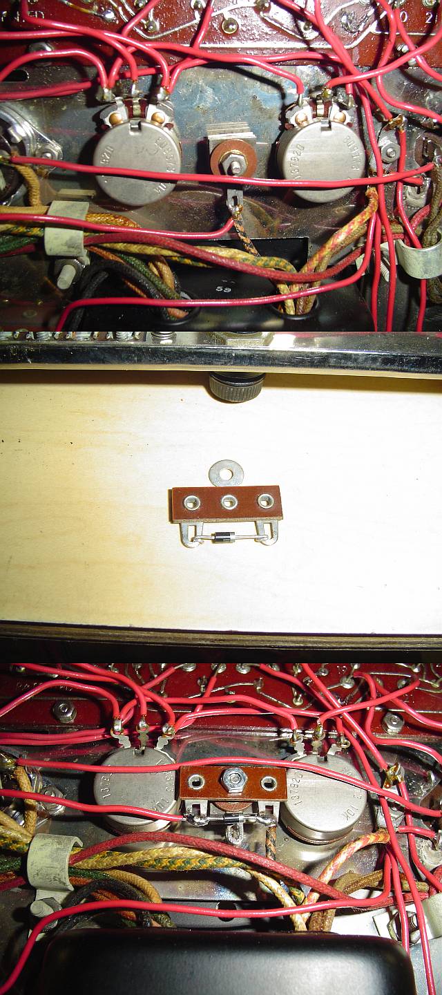
-
TomMcNally - Darling du Jour
- Posts: 2729
- Joined: Sat Nov 19, 2005 2:19 pm
- Location: Northfield, NJ
Re: ST-70 build combining kits, help needed
![]() by petercapo » Tue Apr 26, 2016 3:15 pm
by petercapo » Tue Apr 26, 2016 3:15 pm
It doesn’t really matter if
1) a wire goes from the PCB to lug 6 with the resistor from lug 6 to lug 5
or if
2) the resistor goes from the PCB to lug 5
There is no internal connection in the EL34 at pin 6. Pin/lug 6 are just hanging in space and can therefore serve as a connection point for anything you like inside the amp.
1) a wire goes from the PCB to lug 6 with the resistor from lug 6 to lug 5
or if
2) the resistor goes from the PCB to lug 5
There is no internal connection in the EL34 at pin 6. Pin/lug 6 are just hanging in space and can therefore serve as a connection point for anything you like inside the amp.
- petercapo
- Posts: 36
- Joined: Fri May 28, 2010 11:51 am
Re: ST-70 build combining kits, help needed
![]() by Aljaheejus » Thu Apr 28, 2016 11:23 pm
by Aljaheejus » Thu Apr 28, 2016 11:23 pm
Thanks. Have to get some real work done before I can get back to the workbench. Will post updates, and probably have more questions.
- Aljaheejus
- Posts: 25
- Joined: Thu Jun 03, 2010 8:33 pm
Re: ST-70 build combining kits, help needed
![]() by Aljaheejus » Sun May 08, 2016 2:53 pm
by Aljaheejus » Sun May 08, 2016 2:53 pm
So, I have some progress to report on this bastard (ST-70 chassis, Dynaco A470 OTs, toroidal power transformer, Triode Cap Board, DIYtube driver board). I installed the 1/4W 1K resistors on the EL34s, using pin 5-6 for these. I installed the 10R 1/4W from pins 8 to a common ground post I made per pair (uninsulated L-shaped wires seen in the photo of underside.)
I am mainly worried about the Resistances and Voltages, see below.
Powers up, and annoyingly hums. Biasing went fairly smoothly. I could use some guidance on tracking down the hum, but first I should say that the resistance and voltages are, in some cases, way off of the DIYtube charts. I don't know how to gauge which of these may be problematic, and which may be due to the non-Dynaco-spec PT and CAP board sections. I used shorting plugs on the inputs, and have a pair of vintage Dynaco A10 speakers (8 ohm) connected for testing. First I used some power resistors on the speaker outs, but then connected the speakers.
The PT wires for the output tubes pins 2 & 7 were only long enough to wire as you see, on some angles, so they are running close to the 5AR4 socket and wires from the choke.
I have a new choke, but did not install. Is there any advantage to using a new one?
My Resistances and Voltages are annotated on the attached images from the DIYtube Instructions.
- resistances-1.jpg (215.52 KiB) Viewed 29686 times
- voltages-1.jpg (178.85 KiB) Viewed 29686 times
- Attachments
-
- 20160508_013954-mod.jpg (468.68 KiB) Viewed 29686 times
-
- 20160508_001512-mod.jpg (523.38 KiB) Viewed 29686 times
- Aljaheejus
- Posts: 25
- Joined: Thu Jun 03, 2010 8:33 pm
Re: ST-70 build combining kits, help needed
![]() by TomMcNally » Sun May 08, 2016 4:36 pm
by TomMcNally » Sun May 08, 2016 4:36 pm
Before we go too far .... does it play music ? Your ohm meter readings on the 12AX7 pin 2 and 7 look like you have the RCA jacks shorted ?
-
TomMcNally - Darling du Jour
- Posts: 2729
- Joined: Sat Nov 19, 2005 2:19 pm
- Location: Northfield, NJ
Re: ST-70 build combining kits, help needed
![]() by Aljaheejus » Sun May 08, 2016 5:04 pm
by Aljaheejus » Sun May 08, 2016 5:04 pm
Yes, it plays music! Thanks. Yes the RCA inputs were shorted. I just removed the shorting plugs and pins 2 and 7 on 12AX7 read 0.468 M.
- Aljaheejus
- Posts: 25
- Joined: Thu Jun 03, 2010 8:33 pm
26 posts
• Page 1 of 2 • 1, 2
Who is online
Users browsing this forum: No registered users and 1 guest