Poco a poco accelerando ...
Have solved two problems. Lost interest a few years ago when nothing seemed to work when I turned the amp on. The dualcolored LED that indicated HV on/off was lost and the circuitry controlling the delayed switching of HV wasn't working; I had accidently switched the BC549 and BC559 transistors.
Yesterday I soldered the correct transistors in correct places and noticed the only purpose of the transistors is to change color of the LED. That left me with the problem of the non-functioning turn-on delay. Quickly ruled out an electrolytic that is slowly charged and hooked to an imput of a schmitt trigger. Leakiy as it was it was never charged enough. Now that part is working but only two of the four 6L6s are heated up. Heater wires faulty??
Currawong
75 posts
• Page 4 of 5 • 1, 2, 3, 4, 5
Re: Currawong
![]() by soundbrigade » Sat Sep 02, 2017 4:37 am
by soundbrigade » Sat Sep 02, 2017 4:37 am
Magnus
"It is always more difficult to fight against faith than against knowledge."
"It is always more difficult to fight against faith than against knowledge."
-

soundbrigade - KT88
- Posts: 1760
- Joined: Mon Jan 28, 2008 4:57 am
- Location: Little Paris, Sweden
Re: Currawong
![]() by TomMcNally » Sat Sep 02, 2017 3:28 pm
by TomMcNally » Sat Sep 02, 2017 3:28 pm
Magnus -
Is there a schematic online for this amp ? I was going to see how the heaters were hooked up, but I can't find anything.
I re-read your old posts, and had forgotten you also put the motorized potentiometer on the wrong side of the board. What a mess it was fixing that on my first Budgie preamp.
... tom
-

TomMcNally - Darling du Jour
- Posts: 2729
- Joined: Sat Nov 19, 2005 2:19 pm
- Location: Northfield, NJ
Re: Currawong
![]() by soundbrigade » Sun Sep 03, 2017 12:47 am
by soundbrigade » Sun Sep 03, 2017 12:47 am
Here are the schematics and please do't scream in fear ... 
http://www.pastisch.se/HF/Cong_AMP.jpg
http://www.pastisch.se/HF/Cong_PSU.jpg
There are several issues that I don't understand. In whole, why do it so fr*gging complicated. Reading the papers, there's a note on cathode stripping, but couldn't just the delay and a relay do the trick. And the switching arrangement to speakers/headphones. A lot of floobydust that may cause problems.
And some may ask why in heavens name I built the stuff. The only answer I can give is that I was intrigued and got curious blue, green and yellow.
Anyway, a fuse is blown (HV) and I will pull out the 6L6s and try to find out where the signal is heading - speakers or headphones.
Magnus
"It is always more difficult to fight against faith than against knowledge."
"It is always more difficult to fight against faith than against knowledge."
-
soundbrigade - KT88
- Posts: 1760
- Joined: Mon Jan 28, 2008 4:57 am
- Location: Little Paris, Sweden
Re: Currawong
![]() by EWBrown » Sun Sep 03, 2017 11:07 am
by EWBrown » Sun Sep 03, 2017 11:07 am
The 6L6 heaters are wired in series, to allow operating with 12V. So, check that the tube socket solder / wiring connections are good,
and that both 6L6s have good filaments. Simple ohm meter continuity test.
I'd be careful using 100 Volt line matching transformers as OPTs with 308VDC B+, and the plate current that the 6L6s will consume,
as line matchers aren't normally made for handling High Voltage DC on their primary windings, They are designed (and have internal insulation)
for a maximum 100 VAC audio signal (plus some safety margin) Also, if these specified OPTs are rated for 15W, the primary winding will be seriously unbalanced,
though the 10W tap, rather than the 15W tap, work well, and be properly balanced. .
With this transformer, 1.25W would be equivalent to 8K; 2.5W would correspond to 4K; 5W would be 2K; which is correct for the center tap,
10W would be 1K, which would be correct value; 15W would be 666 ohms ; and COM ( 0K) would be the "lower" plate connection. 666 is the "odd man out"

http://www.altronics.com.au/p/m1115-8-o ... ansformer/
I just noticed that the V2 / V6 phase splitter plate resistors are of widely different values (120K and 220K),
normally these would have the same value, or at most, have no more than 10% different resistance values. .
And the common connected emitters, err, cathodes tail resistor is of rather low resistance, but then, since on the left side of the PI tube, the plate current is 0.275 mA, and the right side, 0.15 mA, presuming that the indicated voltages are indeed correct. Take the square tire, and buff the corners down, for smoother operation
Maybe they did this intentionally to "fudge" the phase splitter into working into an unbalanced OPT primary?
Other than those items, it looks like a fairly conventional 6L6 UL PP design. One that was designed by a committee of soiled state circuit experts
/ed B in NC
and that both 6L6s have good filaments. Simple ohm meter continuity test.
I'd be careful using 100 Volt line matching transformers as OPTs with 308VDC B+, and the plate current that the 6L6s will consume,
as line matchers aren't normally made for handling High Voltage DC on their primary windings, They are designed (and have internal insulation)
for a maximum 100 VAC audio signal (plus some safety margin) Also, if these specified OPTs are rated for 15W, the primary winding will be seriously unbalanced,
though the 10W tap, rather than the 15W tap, work well, and be properly balanced. .
With this transformer, 1.25W would be equivalent to 8K; 2.5W would correspond to 4K; 5W would be 2K; which is correct for the center tap,
10W would be 1K, which would be correct value; 15W would be 666 ohms
; and COM ( 0K) would be the "lower" plate connection. 666 is the "odd man out" http://www.altronics.com.au/p/m1115-8-o ... ansformer/
I just noticed that the V2 / V6 phase splitter plate resistors are of widely different values (120K and 220K),
normally these would have the same value, or at most, have no more than 10% different resistance values. .
And the common connected emitters, err, cathodes tail resistor is of rather low resistance, but then, since on the left side of the PI tube, the plate current is 0.275 mA, and the right side, 0.15 mA, presuming that the indicated voltages are indeed correct. Take the square tire, and buff the corners down, for smoother operation
Maybe they did this intentionally to "fudge" the phase splitter into working into an unbalanced OPT primary?
Other than those items, it looks like a fairly conventional 6L6 UL PP design. One that was designed by a committee of soiled state circuit experts
/ed B in NC
Last edited by EWBrown on Mon Sep 04, 2017 5:48 pm, edited 3 times in total.
Real Radios Glow in the Dark
-
EWBrown - Insulator & Iron Magnate
- Posts: 6389
- Joined: Wed Mar 19, 2003 6:03 am
- Location: Now located in Clay County, NC !
Re: Currawong
![]() by Geek » Sun Sep 03, 2017 1:07 pm
by Geek » Sun Sep 03, 2017 1:07 pm
EWBrown wrote:... line matchers aren't normally made for handling High Voltage DC on their primary winding...
Line matchers aren't gapped, either.
At least I've never run across one that is

-= Gregg =-
Fine wine comes in glass bottles, not plastic sacks. Therefore the finer electrons are also found in glass bottles.
Fine wine comes in glass bottles, not plastic sacks. Therefore the finer electrons are also found in glass bottles.
-
Geek - KT88
- Posts: 3585
- Joined: Sun Oct 21, 2007 3:01 am
- Location: Chilliwack, British Columbia
Re: Currawong
![]() by soundbrigade » Sun Sep 03, 2017 2:29 pm
by soundbrigade » Sun Sep 03, 2017 2:29 pm
I read your notes and I guess you are right. I do, however hope that the transformer is made with a great deal of "headroom" for excess voltages and currents. The Silicon Chip people don't like tubes, which can be seen in their designs. The odd Mudlark (cathode coupled around 6L6) amp is a real mess and a preamp (line) is built around a 12AX7.

I am, at the moment most concerned when it comes to circuitry that normally is no standard in good tube amps. I am struggling with this guy and what it up and running so I can take care of another 6L6PP-amp (that may run with 6P3S-E or VT1075 ).
).
I am, at the moment most concerned when it comes to circuitry that normally is no standard in good tube amps. I am struggling with this guy and what it up and running so I can take care of another 6L6PP-amp (that may run with 6P3S-E or VT1075
).Magnus
"It is always more difficult to fight against faith than against knowledge."
"It is always more difficult to fight against faith than against knowledge."
-
soundbrigade - KT88
- Posts: 1760
- Joined: Mon Jan 28, 2008 4:57 am
- Location: Little Paris, Sweden
Re: Currawong
![]() by EWBrown » Mon Sep 04, 2017 5:18 pm
by EWBrown » Mon Sep 04, 2017 5:18 pm
I see another potential SNAFU / FUBAR in the power supply design - if one were to put a jumper across LK6 (bottom of the schematic),
that would effectively short out the lower left diode in the FW Bridge, and that is NEVER a good thing...
Another vexatious little weirdie... They ground one side of the 12VAC filament winding, then let "VEE"
float thru the 10K resistor, (unless LK6 is inserted, then the whole issue goes BOOM, or perhaps only the 2 amp fuse just goes
POP!).
Just remember, in these "floobydust" designs, the fuse is generally well protected by the most expensive and hard to obtain solid state component 

If I were to try to build one of these strange Australian birds, I'd delete anything that contains a transistor or IC, and ditch the fancy schmancy
automatic "headphones plugged in" detector circus, errr circuit Too much "floobydust" = too many weak links in the chain. All that
"magic blue smoke" just waiting to escape from its confinement
That is why I'll adhere to the KISS principle, and just toss this one together:

which uses a 50-60 year old time-tested design which they clearly purloined from Dynaco: (with a couple differing resistor values)

/ed B in NC
that would effectively short out the lower left diode in the FW Bridge, and that is NEVER a good thing...
Another vexatious little weirdie... They ground one side of the 12VAC filament winding, then let "VEE"
float thru the 10K resistor, (unless LK6 is inserted, then the whole issue goes BOOM, or perhaps only the 2 amp fuse just goes
POP!).
Just remember, in these "floobydust" designs, the fuse is generally well protected by the most expensive and hard to obtain solid state component
If I were to try to build one of these strange Australian birds, I'd delete anything that contains a transistor or IC, and ditch the fancy schmancy
automatic "headphones plugged in" detector circus, errr circuit
Too much "floobydust" = too many weak links in the chain. All that "magic blue smoke" just waiting to escape from its confinement
That is why I'll adhere to the KISS principle, and just toss this one together:
which uses a 50-60 year old time-tested design which they clearly purloined from Dynaco: (with a couple differing resistor values)
/ed B in NC
Real Radios Glow in the Dark
-
EWBrown - Insulator & Iron Magnate
- Posts: 6389
- Joined: Wed Mar 19, 2003 6:03 am
- Location: Now located in Clay County, NC !
Re: Currawong
![]() by TomMcNally » Mon Sep 04, 2017 6:31 pm
by TomMcNally » Mon Sep 04, 2017 6:31 pm
Interesting that you bring the "early Dynaco" board up. I ordered a couple of those to mess with. I got one bare and one with the kit of parts in your pic.
I built one 6 years ago and it sounded pretty good.


I built one 6 years ago and it sounded pretty good.
-
TomMcNally - Darling du Jour
- Posts: 2729
- Joined: Sat Nov 19, 2005 2:19 pm
- Location: Northfield, NJ
Re: Currawong
![]() by soundbrigade » Mon Sep 04, 2017 11:36 pm
by soundbrigade » Mon Sep 04, 2017 11:36 pm
I am tossing that one together right now.
Got the last PCB-monted octal socket and two missing caps yesterday. Have to search for a mains transformer.
Will lokk into the issues you are talking aout (the links).
Got the last PCB-monted octal socket and two missing caps yesterday. Have to search for a mains transformer.
Will lokk into the issues you are talking aout (the links).
Magnus
"It is always more difficult to fight against faith than against knowledge."
"It is always more difficult to fight against faith than against knowledge."
-
soundbrigade - KT88
- Posts: 1760
- Joined: Mon Jan 28, 2008 4:57 am
- Location: Little Paris, Sweden
Re: Currawong
![]() by soundbrigade » Tue Sep 05, 2017 12:33 am
by soundbrigade » Tue Sep 05, 2017 12:33 am
Also, the coice of tubes are a bit odd. ECC83/12AX7 isn't the most unobtainable tubes in the world, but also not the most "well-sounding" either. A choice of other tubes like 12AU7 and 12AY7 or even a trioded EF86/6267 as input tube sounds like a better choice. I'm not the one who likes fiddling with things that work, but it had been intriguing to make a subtle change of components here and there.
I made a note that the Silicon Chip people don't like tubes, that's propably why they construct strange and, for the tubes, humiliating stuff.
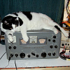
This is a poor pic of another amp, published in 2005. I have mentioned it but my memory thought it was a cathode-coupled one. It's actually a ParaFeed. The pic is bad, the only one I found on the www. Tried once to understand it but couldn't.

I made a note that the Silicon Chip people don't like tubes, that's propably why they construct strange and, for the tubes, humiliating stuff.
This is a poor pic of another amp, published in 2005. I have mentioned it but my memory thought it was a cathode-coupled one. It's actually a ParaFeed. The pic is bad, the only one I found on the www. Tried once to understand it but couldn't.
Magnus
"It is always more difficult to fight against faith than against knowledge."
"It is always more difficult to fight against faith than against knowledge."
-
soundbrigade - KT88
- Posts: 1760
- Joined: Mon Jan 28, 2008 4:57 am
- Location: Little Paris, Sweden
Re: Currawong
![]() by EWBrown » Tue Sep 05, 2017 8:58 pm
by EWBrown » Tue Sep 05, 2017 8:58 pm
Ouch! another unnecessarily complicated design  But then, Mudlarks are another strange breed of bird...
Parafeed is a good, tried and true method, its chief advantage is that it removes any DC from the OPT primary,
so that an airgapped OPT is not required. The input / driver circuit is just plain strange, and WTH is that transistor there for
(I know, they're doing some strange voltage shifting thing, so that the output stage can be operated as quasi-fixed bias,
but still have some cathode resistance). There are simpler methods to accomplish that.
IF they were attempting to use screen grid drive on the 6L6s, then this hybrid design would be reasonable,
as a large signal voltage swing, with grid current would be required to properly drive them.
Once again, the soiled state design committee attempts to take on tube amp design, with the expected results
I'd just use a 12AT7 SRPP driver, and change the 6L6s' cathode resistor for proper Class A operation. No floobydust or blue smoke needed
/ed B
But then, Mudlarks are another strange breed of bird...Parafeed is a good, tried and true method, its chief advantage is that it removes any DC from the OPT primary,
so that an airgapped OPT is not required. The input / driver circuit is just plain strange, and WTH is that transistor there for
(I know, they're doing some strange voltage shifting thing, so that the output stage can be operated as quasi-fixed bias,
but still have some cathode resistance). There are simpler methods to accomplish that.
IF they were attempting to use screen grid drive on the 6L6s, then this hybrid design would be reasonable,
as a large signal voltage swing, with grid current would be required to properly drive them.
Once again, the soiled state design committee attempts to take on tube amp design, with the expected results
I'd just use a 12AT7 SRPP driver, and change the 6L6s' cathode resistor for proper Class A operation. No floobydust or blue smoke needed
/ed B
Real Radios Glow in the Dark
-
EWBrown - Insulator & Iron Magnate
- Posts: 6389
- Joined: Wed Mar 19, 2003 6:03 am
- Location: Now located in Clay County, NC !
Re: Currawong
![]() by soundbrigade » Tue Sep 05, 2017 11:35 pm
by soundbrigade » Tue Sep 05, 2017 11:35 pm
Regarding LK6:
Does that change anything?
There was a special note about LK6 on page 38 of the November 2014 issue. LK6 must not be fitted when two transformers are used. LK6 is only used where a single transformer is employed, as described in the October 2016 issue.
Does that change anything?
Magnus
"It is always more difficult to fight against faith than against knowledge."
"It is always more difficult to fight against faith than against knowledge."
-
soundbrigade - KT88
- Posts: 1760
- Joined: Mon Jan 28, 2008 4:57 am
- Location: Little Paris, Sweden
Re: Currawong
![]() by soundbrigade » Wed Sep 06, 2017 2:42 pm
by soundbrigade » Wed Sep 06, 2017 2:42 pm
@ Mr Brown & McNally:
Got the input in another forum that the 6V6 amp needs some input voltage(s) and I almost considered a simple preamp stage for this amp (the 6V6 one). But I guess a modetn CD-player is capable of an output voltage up to 2V. So how have you arranged the driving of your amplifiers?
Got the input in another forum that the 6V6 amp needs some input voltage(s) and I almost considered a simple preamp stage for this amp (the 6V6 one). But I guess a modetn CD-player is capable of an output voltage up to 2V. So how have you arranged the driving of your amplifiers?
Magnus
"It is always more difficult to fight against faith than against knowledge."
"It is always more difficult to fight against faith than against knowledge."
-
soundbrigade - KT88
- Posts: 1760
- Joined: Mon Jan 28, 2008 4:57 am
- Location: Little Paris, Sweden
Re: Currawong
![]() by TomMcNally » Wed Sep 06, 2017 7:35 pm
by TomMcNally » Wed Sep 06, 2017 7:35 pm
Sorry, I don't have a good answer to the question. I built two of them, listened to them probably at that time connected to my Adcom SS preamp, then sold them on eBay. One of them went to Russia where the tubes came from. What output transformers are you using on the 6V6 amp ? I'd like to find something cheap, but nothing so far. I got my boards yesterday, one bare and one with parts. I haven't planned anything yet.
... tom
... tom
-
TomMcNally - Darling du Jour
- Posts: 2729
- Joined: Sat Nov 19, 2005 2:19 pm
- Location: Northfield, NJ
Re: Currawong
![]() by Geek » Wed Sep 06, 2017 9:49 pm
by Geek » Wed Sep 06, 2017 9:49 pm
EWBrown wrote:Ouch! another unnecessarily complicated design
I thought it was fo' geetah, yo!

-= Gregg =-
Fine wine comes in glass bottles, not plastic sacks. Therefore the finer electrons are also found in glass bottles.
Fine wine comes in glass bottles, not plastic sacks. Therefore the finer electrons are also found in glass bottles.
-
Geek - KT88
- Posts: 3585
- Joined: Sun Oct 21, 2007 3:01 am
- Location: Chilliwack, British Columbia
75 posts
• Page 4 of 5 • 1, 2, 3, 4, 5
Who is online
Users browsing this forum: No registered users and 4 guests