Hot little Darling from last night !

the thermionic watercooler

Hot little Darling from last night !

Postby TomMcNally » Tue Apr 08, 2008 2:48 pm

Well I got the bug (finally) to build some amps. I built a 12SL7 driver Darling last night, which will make its way to eBay once Sal sells his.

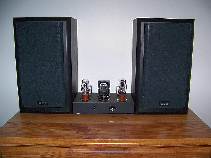
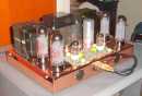
These are a great little amp, and an easy build ... obviously, I've been around the block with these a few dozen times. The sheet metal took about an hour and a half, and about two hours to wire it up.

More pics at http://tmamps.com

Image
User avatar
TomMcNally
Darling du Jour
 
Posts: 2729
Joined: Sat Nov 19, 2005 2:19 pm
Location: Northfield, NJ

Postby Sal Brisindi » Tue Apr 08, 2008 7:43 pm

Nice job Tom,

I can't build them as fast as you can but building the 2nd one was faster. Maybe after my 24th one, I can get the build time down to 3 or 4 hours...

I have 6 people watching my Darling on ebay, well really 5 as you don't count unless you want to buy mine.... Yellow_Light_Colorz_PDT_02

I just got a deal on 7 NOS 1626's for $5.00 a piece, 12SL7's for $3.00 each pretty much the going rate). I will buy them and hold on to them for future Darlings.... I think I have 5 or 6 1626's in my stock somewhere in my dungeon....

I have been listening to my Darling every night, I am really enjoying that little amp!

Sal

Image
User avatar
Sal Brisindi
KT88
 
Posts: 374
Joined: Thu Mar 22, 2007 5:21 am
Location: Freehold N.J.

Nice

Postby jduffy » Wed Apr 09, 2008 9:24 am

Great job as usual.

Tom, what does the BOM look like for one of these little devils?

Any hum in these?

It's so cute inside the way you have it set up. So clean and minimalistic looking. Double that for the top as well. You really have it down to a science or an assembly line!
User avatar
jduffy
 
Posts: 43
Joined: Sat Jan 06, 2007 2:52 pm
Location: SoCal

Don't bogart that amp, my friend, pass it over to me...

Postby EWBrown » Wed Apr 09, 2008 9:37 am

These are what I call "Bogart Amps" 'cuz they're so Hum-free Yellow_Light_Colorz_PDT_04

/ed B in NH
Real Radios Glow in the Dark
User avatar
EWBrown
Insulator & Iron Magnate
 
Posts: 6389
Joined: Wed Mar 19, 2003 6:03 am
Location: Now located in Clay County, NC !

Postby TomMcNally » Wed Apr 09, 2008 8:19 pm

Darling 1626/12SL7 amplifier parts list

2 - 1626 tubes
1 - 12SL7 tube
3 - octal sockets
1 - Hammond 269EX power transformer
1 - Hammond 156R choke
2 - Hammond 125CSE or Edcor XSE15-8-5K output transformer
1 - Chassis and bottom plate (12 x 8 x 3 is nice)

1 - fuse holder
1 - 1 amp fuse
1 - SPST power switch
1 - IEC power jack or straight power cord
2 - RCA jacks
2 - speaker terminals
some terminal strips to mount parts on

2 - high voltage diodes - 1N4001 or 1N5408
2 - 6 amp 50 PIV or better diodes

2 - 47 mfd 350 volt electrolytics
1 - 100 mfd 350 volt electrolytic
2 - 2200 mfd 35 volt electrolytics
2 - 100 mfd 25 volt electrolytics
2 - 100 mfd 100 volt electrolytics
2 - .22 or .33 400 volt coupling capacitors

1 - 100k logarithmic taper audio potentiometer
1 - 1 ohm 5 or 10 watt resistor
2 - 1K 1 or 2 watt resistors
2 - 1K 3 watt resistors
1 - 7.5K 3 watt resistor
2 - 100K 2 watt resistors
2 - 220K 1/2 or 1 watt resistors

Construction notes:

Mount the audio transformers at opposite angles than the power
transformer. Use a heavy bus wire (like a piece of house wire)
for a ground bus, don't ground things to the chassis. The only
thing you will ground to the chassis is the third wire of the
power cord, and you can ground the RCA jacks to the chassis, and
then connect your ground bus to that. Most components can mount
from tube pin to tube pin, except for the high voltage and filment
supply diodes and capacitors, which can mount on terminal strips.
The center tap lead of the power transformer should be soldered
to the ground bus at the same point as the minus ends of the
electrolytic capacitors. Remember, every amplifier is unique.
Start with the power supply, and filament leads, then output
transformers, and work your way back so the input is LAST.
User avatar
TomMcNally
Darling du Jour
 
Posts: 2729
Joined: Sat Nov 19, 2005 2:19 pm
Location: Northfield, NJ

Postby TomMcNally » Wed Apr 09, 2008 8:52 pm

Image
User avatar
TomMcNally
Darling du Jour
 
Posts: 2729
Joined: Sat Nov 19, 2005 2:19 pm
Location: Northfield, NJ

Postby DerekVa » Wed Apr 09, 2008 11:02 pm

Tom - I gotta ask, what's your secret for making Hammond chassis(es) look so darn good. Every time I try and do that, it looks like Charlie Brown's ghost costume.

Any tips? Please?

-D
DerekVa
 
Posts: 226
Joined: Sat Jun 10, 2006 12:43 am
Location: Woodinville, WA

Postby EWBrown » Thu Apr 10, 2008 5:09 am

It just takes practice, practice, practice.... My earlier HB amps looked like they (barely) survived the Battle of Stalingrad, now I am approaching (but not quite yet achieving) Tom's workmanship standards.

I used to joke that I'd be better off using a pistol or shotgun to do my chassis drilling and punching Yellow_Light_Colorz_PDT_04 Yellow_Light_Colorz_PDT_07

I'm still at the "soviet cold war military surplus" appearance stage, but it is much better than my earliest attempts. Yellow_Light_Colorz_PDT_02

The black powder-coated finish on the steel Hammond chassis is fairly durable, and somewhat forgiving of minor blunders and boo-boos, much more so than the gray painted chassis. If I paint a bare chassis, I finally got the procedures figured out for a good finish, but then I always seem to manage to put at least one ding, gouge or scratch in it before I'm completed, and these are usually right up front, in plain view Yellow_Light_Colorz_PDT_21 Yellow_Light_Colorz_PDT_09

/ed B in NH / NC
Real Radios Glow in the Dark
User avatar
EWBrown
Insulator & Iron Magnate
 
Posts: 6389
Joined: Wed Mar 19, 2003 6:03 am
Location: Now located in Clay County, NC !

Postby TomMcNally » Thu Apr 10, 2008 8:43 am

Here is how I do it ...

Ground rules:

remember what Steve from Angela says ... "don't drill any holes until you have ALL of the parts in hand"

get a little bottle of automotive touch up paint (just in case)

keep it clean ! don't grind metal into the chassis !

Tools I use:

Makita battery powered hand drill
sharp bits (no bits bigger than 1/4" in - they distort)
UniBit brand bit (not cheap import)
metal drill guide to size holes needed
General brand Automatic Center punch
white china marker (grease pencil)
Stanley slide type caliper
small steel square
Greenlee Chassis (not conduit) punches 1/2" and 1 1/16"
(obviously sizes depend on your sockets)
Dremel tool with Gyros cutoff wheel (NOT Dremel brand)
a couple of files (just in case)

lay the chassis on a folded newspaper
if using an IEC power connector, mark a 1" x 3/4" box with the
china marker - then cut it with the Dremel ...
lay out your parts for the front, center nicely, mark with
the china marker ... center punch a couple of times,
drill a very small pilot hole first - NEVER forget this
drill holes to required size
shake metal bits on newspaper, shake newspaper over trashcan
(no scratches next step)
flip chassis over - same steps for the back
the 1/2" chassis punch is great for binding post holes
eye up the front and back panel parts or test fit them and
make sure parts on top will not hit them !!!
repeat for the top - being sure to start with tiny pilot holes -
the reason for this is that the small bit will find the center of
the centerpunch quickly and accurately !
I never drill bigger that 1/4" with a twist bit - if you don't have a
Greenlee for the size you need, use the UniBit
Always shake off the metal bits, don't let them grind in !
After all holes are drilled and punched, use a larger bit to hit
each hole QUICKLY from both sides to clean up the burr
Use the Dremel to clean up major burrs also ...
Oh yeah - when using chassis punch, put the cutting part on the
OUTSIDE of the chassis for a cleaner cut (the bolt side on the inside)
Use the steel square to line things up and keep things symmetrical

I also really like to use all stainless Phillips hardware, with the nuts
with the captive washer called "kepnuts" ... they go on very fast and
you don't usually have to hold the bottom ... DON'T tighten too tight
as you may distort the steel

Obviously, with 22 of these under my belt, it goes faster, I made a
Darling last night and the metalwork only took an hour and 10 minutes.

I find the Hammond steel chassis much easier to work with than aluminum, the holes are cleaner and not "gummy"
User avatar
TomMcNally
Darling du Jour
 
Posts: 2729
Joined: Sat Nov 19, 2005 2:19 pm
Location: Northfield, NJ

Postby DerekVa » Thu Apr 10, 2008 10:46 am

Wow, Tom! Thanks!

Now I just need to convince the wife that I need more tools! Yellow_Light_Colorz_PDT_07

Any opinion on nibblers for IEC connector holes?
DerekVa
 
Posts: 226
Joined: Sat Jun 10, 2006 12:43 am
Location: Woodinville, WA

Postby TomMcNally » Thu Apr 10, 2008 10:56 am

Derek ...

I used Nibblers for years - but no more. The Dremel with the Gyros brand cutoff wheel is amazing. Granted, I have practice ... but I can cut a perfect hole for an IEC connector in about a minute. The Nibblers require lots of time and you wind up with a sore hand ! I got a nice Dremel for Christmas a while back, and never found a real use for it, until Shannon suggested it was a good way to cut holes in chassis for transformers. It is amazing for zipping through steel, aluminum isn't quite as easy, and don't use it on plastic without going slow, it melts !

I haven't spent a fortune on tools, probably the assortment of Greenlee Chassis Punches cost the most, but I now realize I don't need as many sizes as I have, I only use about 4 of them.
User avatar
TomMcNally
Darling du Jour
 
Posts: 2729
Joined: Sat Nov 19, 2005 2:19 pm
Location: Northfield, NJ

Postby EWBrown » Thu Apr 10, 2008 11:33 am

Nibblers are a real pain in the a..., er, hand (and wrist)....

I'll use them on aluminum, but not on steel, unless one wants to develop a major case of Carpal Tunner Syndrome :o or else end up with "Popeye" looking forearms... Yellow_Light_Colorz_PDT_04

Another trick I use for the black powder-coated steel chassis, is to cover the top and sides with the blue "painter's" masking tape, and then mark that up, and then do your center punching. The blue tabpe is good, because it doesn't leave behind any adhesive residue goo.

The tape can be left in place, if there is no drilling to be done in a given area, and the tape serves to protect the finish from minor nicksches, but NOT major drill bit "slip & gouge" incidents Yellow_Light_Colorz_PDT_21

I've used the "conduit" Greenlee punch set, in cases where I needed a 7/8 inch or 1 3/32 inch diameter hole, and the larger diameter ones are just the right size for mounting the James 6112 /6113 /6115 OPTs. These punches also have a ball-bearing driving screw, so it makes the job easier, less friction to overcome...

/ed
Real Radios Glow in the Dark
User avatar
EWBrown
Insulator & Iron Magnate
 
Posts: 6389
Joined: Wed Mar 19, 2003 6:03 am
Location: Now located in Clay County, NC !

Postby mesherm » Thu Apr 10, 2008 12:21 pm

I have to agree with Tom and Ed on the nibbler issue. They are more trouble than they are worth. I use the Dremel and abrasive blade method and I use mostly steel chassis. Once you get the hang of it you can make a nice square or rectangular hole in almost no time at all. Add in a few chassis punches and a unibit and you have about all you need. I have learned to center-punch and drill small pilot holes before using a unibit.
Mike's N-1 Rule: When looking for N number of components to finish a job, you have a 95% chance of only finding N-1 of them.
User avatar
mesherm
KT88
 
Posts: 1232
Joined: Fri Aug 27, 2004 10:33 pm
Location: Alvin Texas

Postby Gingertube » Thu Apr 10, 2008 5:48 pm

Hint:
When I build stuff into a Hammond Chassis I cover the chassis with low tack masking tape. Mark all holes on the masking tap. Cut / drill through the tape into the metal. When mounting transformers, tube sockets etc. remove just enough of the tape to mount the component. Last step AFTER everything is up and running is to remove the last of the masking tape.
Oh and I have a paint brush on the bench which I use to brush away bits of metal reasonably often - after drilling say 3 or 4 holes.

The tape protects the chassis from dings and scratches while working.

Cheers,
Ian
Gingertube
 
Posts: 245
Joined: Thu Oct 05, 2006 10:27 pm
Location: Adelaide, South Oz

Postby TomMcNally » Fri Apr 11, 2008 8:18 am

Here's another Darling I finished up last night ...

It looks just like the other one.

Image
Image
User avatar
TomMcNally
Darling du Jour
 
Posts: 2729
Joined: Sat Nov 19, 2005 2:19 pm
Location: Northfield, NJ

Next

Return to diy hifi

Who is online

Users browsing this forum: No registered users and 1 guest