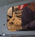
just got a new variac, staco 1010ct. i need to wire it in/out so i can use it; i guess it had been hard wired to a machine. here are a few pics:
http://s265.photobucket.com/albums/ii229/nyazzip/
the plug on the end of the cable matches an el34 tube base exactly. my questions are:
which wires go where when i attach a 3 prong 120VAC input plug to it? and how do i wire a 3 prong output recepticle to it? in its current state, terminals 5 and 2 are "blank", so i'm guessing thats the output.
also, will any part of the base be dangerous to touch when in operation? i plan on putting a plate over it eventually
also, can i damage any of my modern tube amps by "browning them out"? this is, after all, the reason i wanted a variac in the first place... regards
wiring a variac
9 posts
• Page 1 of 1
wiring a variac
![]() by nyazzip » Fri Feb 22, 2008 2:26 pm
by nyazzip » Fri Feb 22, 2008 2:26 pm
Last edited by nyazzip on Fri Feb 22, 2008 10:54 pm, edited 1 time in total.
-

nyazzip - KT88
- Posts: 1073
- Joined: Wed Jan 09, 2008 1:24 am
![]() by TomMcNally » Fri Feb 22, 2008 2:55 pm
by TomMcNally » Fri Feb 22, 2008 2:55 pm
I would get a standard electrical outlet box and a regular
household "duplex" outlet and a three prong power cord
at the hardware store ...
(or use an old computer cord and cut off the IEC connector)
and wire it up like this ...
cut the octal socket off ...
connect the green wire to the ground lug of the duplex outlet,
and to the ground wire of the power cord.
connect the white lead from the Variac to the neutral
side (silver) of the duplex outlet, and connect the white
from the power cord to the other screw
SPLIT the tab on the "brass" or black side of the duplex
outlet.
Connect the black from the variac AND black from the
power cord on ONE of the brass screws on the duplex
outlet ... that side will be HOT all the time
connect the red from the variac to the other brass screw
on the outlet ... that will be your "Variable" outlet.
It wouldn't be a bad idea to put a 10 amp 250 volt fuse
inline with the incoming BLACK lead of the power cord.
Link to wiring diagram on Staco's site:
http://stacoenergy.com/pdf/installation-drawings/1010BCT.pdf
... tom
-

TomMcNally - Darling du Jour
- Posts: 2729
- Joined: Sat Nov 19, 2005 2:19 pm
- Location: Northfield, NJ
![]() by erichayes » Fri Feb 22, 2008 4:00 pm
by erichayes » Fri Feb 22, 2008 4:00 pm
Your link won't load for me, so I'll give you a generic answer.
The only parts of the device that present a shock hazard are the in/out terminals, themselves (duh), the wiper, and the exposed edge of the winding that the wiper rides on. Since these are all located on the rear and/or side of the frame, a simple open-backed wood box would provide adequate protection in most instances.
The only parts of the device that present a shock hazard are the in/out terminals, themselves (duh), the wiper, and the exposed edge of the winding that the wiper rides on. Since these are all located on the rear and/or side of the frame, a simple open-backed wood box would provide adequate protection in most instances.
Eric in the Jefferson State
- erichayes
- KT88
- Posts: 987
- Joined: Fri Jan 23, 2004 9:01 pm
- Location: McKinleyville CA
Re: wiring a variac
![]() by Ty_Bower » Fri Feb 22, 2008 8:24 pm
by Ty_Bower » Fri Feb 22, 2008 8:24 pm
nyazzip wrote:also, can i damage any of my modern tube amps by "browning them out"? this is, after all, the reason i wanted a variac in the first place...
I don't think so... although I'm not exactly sure myself. It's probably not optimal to run them for prolonged periods of time at less than 115VAC line voltage, but I wouldn't think it should hurt them.
Mostly, the B+ will head towards the low end and consequently distortion will head towards the high end. Heater voltages will also droop, and possibly result in reduced emission. I doubt any of this will cause any permanent damage.
To over-generalize, vacuum tubes are relatively sturdy when it comes to events electrical in nature. Mechanically, they are rather fragile. You can overvolt them, or even apply reverse voltages and often they will walk away unscathed. Drop them on the cement, though, and you can kiss your tubes good-bye. In contrast, solid state transistors will tolerate very little electrical abuse, but stand up well to all sorts of mechanical trauma.
-
Ty_Bower - KT88
- Posts: 1494
- Joined: Wed Mar 21, 2007 2:50 pm
- Location: Newark, DE
![]() by nyazzip » Sat Feb 23, 2008 1:17 am
by nyazzip » Sat Feb 23, 2008 1:17 am
thanks for the input guys
so tom, you say: "SPLIT the tab on the "brass" or black side of the duplex outlet. Connect the black from the variac AND black from the
power cord on ONE of the brass screws on the duplex
outlet ... that side will be HOT all the time. connect the red from the variac to the other brass screw
on the outlet ... that will be your "Variable" outlet."
but splitting the duplex isn't an option on the one i bought. its molded in, can't be done. and, i'm not interested in having a bypassed recepticle anyway. its fine by me if they are both "variaced". so.....now what?
i wired it up anyway, and i just tripped the main input breaker here at the house. i was prepared, and had the flashlight in my pocket though.... i better stop before someone gets hurt
the variac powered a small desktop lamp for a few seconds when the dial was around 60%, but hummed noisily. then i unplugged it, and moved the dial down to maybe 20%, and when i plugged it back in thats when the big boy tripped. what can it all mean....
off to bed, thanks all
-
nyazzip - KT88
- Posts: 1073
- Joined: Wed Jan 09, 2008 1:24 am
![]() by TomMcNally » Sat Feb 23, 2008 11:08 am
by TomMcNally » Sat Feb 23, 2008 11:08 am
Oh jeez ... yeah if you didn't follow the instructions,
the breaker will trip !
All duplex outlets have a tab on the side you can
break off between the two screws ...
BUT .... if you can't ...
do this:
tie the black wire from the power cord and the
black wire from the Variac's cable together
in a wire nut ... do not connect to anything else.
the red wire from the Variac will be the only thing
tied to the brass screw on the duplex outlet
... tom
-
TomMcNally - Darling du Jour
- Posts: 2729
- Joined: Sat Nov 19, 2005 2:19 pm
- Location: Northfield, NJ
![]() by nyazzip » Sat Feb 23, 2008 2:41 pm
by nyazzip » Sat Feb 23, 2008 2:41 pm
here the thing: i already eliminated the cord that came with the variac. it had an octal socket on one end, and at least 5 wires in it. at this point all i'm trying to do is plug the damn thing into a wall, and an octal socket and 5 wires ain't gonna help me do that.
so, i bought a regular 16 gauge 3 prong plug, got it stripped down, green, white black. just need to know where to stick em on the variac, which has terminals numbered 1-5, and a ground lug on the chassis.
i saw the staco schematic. looks purty, but it doesn't help me. hell, the variac itself has a schematic on it. really couldn't be clearer- if you are an electrician.
after that hurdle is cleared, then i can begin the mystery of wiring up the output, which is is a duplex 3 prong recepticle.
i don't think you guys realize the depth of my ignorance here. i have tried to get books from the library and stuff on this, but none of them are in a language that i understand, i.e. english.
can you believe i managed to build a working ST-35? me neither.
spring looks like its around the corner here in chicago. if i had a sugar maple i'd have a tap in it
yee haw
-
nyazzip - KT88
- Posts: 1073
- Joined: Wed Jan 09, 2008 1:24 am
![]() by TomMcNally » Sat Feb 23, 2008 2:58 pm
by TomMcNally » Sat Feb 23, 2008 2:58 pm
Well I can't really make the instructions much clearer.
Connect WHITE of the power cord and WHITE of
the output socket to Pin 1
Connect BLACK of the output socket to Pin 3
Connect BACK of the INPUT power cord to Pin 4
Connect Grounds (Green) of the power cord and
output socket to the case of the Variac
thats it
Connect WHITE of the power cord and WHITE of
the output socket to Pin 1
Connect BLACK of the output socket to Pin 3
Connect BACK of the INPUT power cord to Pin 4
Connect Grounds (Green) of the power cord and
output socket to the case of the Variac
thats it
-
TomMcNally - Darling du Jour
- Posts: 2729
- Joined: Sat Nov 19, 2005 2:19 pm
- Location: Northfield, NJ
9 posts
• Page 1 of 1
Who is online
Users browsing this forum: No registered users and 3 guests