Hey all
I just received my SDS boards from Triode but the Poseidon boards did not come. I'm a bit bummed as I am more than ready to dive into my pair of Mark III's.
I'm pretty much a newb but have been a parts swapper for sometime. I'm hoping to get some help from you all once I can get ahold of the Poseidon boards.
Anyway....glad to be here and looking forward to some DIY'n
New here
21 posts
• Page 1 of 2 • 1, 2
New here
![]() by Rex Everything » Tue Feb 24, 2009 6:54 pm
by Rex Everything » Tue Feb 24, 2009 6:54 pm
- Rex Everything
- Posts: 70
- Joined: Sun Feb 22, 2009 6:26 pm
- Location: Las Vegas
![]() by Brik » Wed Feb 25, 2009 8:35 am
by Brik » Wed Feb 25, 2009 8:35 am
Welcome to the board, Rex.
There are many knowledgeable posters here who can help with many tube projects.
I received lots of great advices and useful information in modifying an S-5 Electronics K-12G tube amp kit and a Dynaco SCA-35.
Have fun with your Mark III project. Yellow_Light_Colorz_PDT_16
/b
There are many knowledgeable posters here who can help with many tube projects.
I received lots of great advices and useful information in modifying an S-5 Electronics K-12G tube amp kit and a Dynaco SCA-35.
Have fun with your Mark III project. Yellow_Light_Colorz_PDT_16
/b
-

Brik - Posts: 204
- Joined: Fri Apr 07, 2006 5:30 pm
- Location: West of Boston
![]() by Rex Everything » Wed Feb 25, 2009 5:59 pm
by Rex Everything » Wed Feb 25, 2009 5:59 pm
Thanks for the welcome. I'm looking forward to the Mark III projects but I have not been able to get an email reply or any one to answer the phone at Triode.
If I don't hear something soon I may have to go another route with the driver boards.
If I don't hear something soon I may have to go another route with the driver boards.
- Rex Everything
- Posts: 70
- Joined: Sun Feb 22, 2009 6:26 pm
- Location: Las Vegas
![]() by TomMcNally » Wed Feb 25, 2009 7:56 pm
by TomMcNally » Wed Feb 25, 2009 7:56 pm
Triode is closed on Wednesdays.
Open 10:30 AM to 5 PM CT, Monday-Tuesday-Thursday-Friday
Open 10:30 AM to 5 PM CT, Monday-Tuesday-Thursday-Friday
-

TomMcNally - Darling du Jour
- Posts: 2729
- Joined: Sat Nov 19, 2005 2:19 pm
- Location: Northfield, NJ
Re: New here
![]() by hilldweller » Thu Feb 26, 2009 8:05 pm
by hilldweller » Thu Feb 26, 2009 8:05 pm
Rex Everything wrote:Hey all
I just received my SDS boards from Triode but the Poseidon boards did not come. I'm a bit bummed as I am more than ready to dive into my pair of Mark III's.
I'm pretty much a newb but have been a parts swapper for sometime. I'm hoping to get some help from you all once I can get ahold of the Poseidon boards.
Anyway....glad to be here and looking forward to some DIY'n
Hi Rex!
My name is Jim and I live In St. Louis as well, Near the Hill area. A year
ago I built a pair of Mark IIIs that I got from Dynakitparts.com. I have the posidon boards as well as the SDS Cap boards, and HV Time delay circuitry. I would be glad to help you with yours. If you are close by and we can meet sometime, You can come and see the ones I built if that will help you. If you need parts sources or any other help, Please let me know and WELCOME!!!
PM me and we can exchange phone numbers. Yellow_Light_Colorz_PDT_11 Yellow_Light_Colorz_PDT_11
Analog is Real! Experience it!
Digital leads to trans humanism. Not good.
Digital leads to trans humanism. Not good.
-
hilldweller - KT88
- Posts: 285
- Joined: Wed Aug 01, 2007 5:28 pm
- Location: St. Louis Missouri USA
Re: New here
![]() by Rex Everything » Thu Feb 26, 2009 8:39 pm
by Rex Everything » Thu Feb 26, 2009 8:39 pm
Nice to know there's someone else in the StL area on this board.
PM sent.
PM sent.
hilldweller wrote:Rex Everything wrote:Hey all
I just received my SDS boards from Triode but the Poseidon boards did not come. I'm a bit bummed as I am more than ready to dive into my pair of Mark III's.
I'm pretty much a newb but have been a parts swapper for sometime. I'm hoping to get some help from you all once I can get ahold of the Poseidon boards.
Anyway....glad to be here and looking forward to some DIY'n
Hi Rex!
My name is Jim and I live In St. Louis as well, Near the Hill area. A year
ago I built a pair of Mark IIIs that I got from Dynakitparts.com. I have the posidon boards as well as the SDS Cap boards, and HV Time delay circuitry. I would be glad to help you with yours. If you are close by and we can meet sometime, You can come and see the ones I built if that will help you. If you need parts sources or any other help, Please let me know and WELCOME!!!
PM me and we can exchange phone numbers. Yellow_Light_Colorz_PDT_11 Yellow_Light_Colorz_PDT_11
- Rex Everything
- Posts: 70
- Joined: Sun Feb 22, 2009 6:26 pm
- Location: Las Vegas
![]() by JW34 » Sat Feb 28, 2009 9:36 am
by JW34 » Sat Feb 28, 2009 9:36 am
Welcome Rex,
I'm about to start on rebuilding my Mark III's as well. It's taken me over a year to gather the parts I need due to life getting in the way. I am now waiting for my bases and transformer covers to come back from getting powdercoated.
I look forward to reading your future posts. The help you get will help me! I know for sure I'll be posting my fair share of questions. This is my first rebuild and I'll need all the help I can get.
You're lucky to have members close to you, USE THEM! I wish I had someone near me in Chicago.
- JW34
- Posts: 106
- Joined: Fri Feb 01, 2008 5:30 pm
- Location: Chicagoland
![]() by Rex Everything » Sat Feb 28, 2009 2:07 pm
by Rex Everything » Sat Feb 28, 2009 2:07 pm
I do feel blessed to have an experienced member so close and so generous.
I think I'm gonna go ahead and get a hold of Shannon and get the boards from him so I can get started on these amps. Planning on doing the SDS boards this evening.
Does anybody happen to have an updated tube chart for the Superior TV-12 tube tester?
I think I'm gonna go ahead and get a hold of Shannon and get the boards from him so I can get started on these amps. Planning on doing the SDS boards this evening.
Does anybody happen to have an updated tube chart for the Superior TV-12 tube tester?
- Rex Everything
- Posts: 70
- Joined: Sun Feb 22, 2009 6:26 pm
- Location: Las Vegas
![]() by hilldweller » Sun Mar 01, 2009 4:40 pm
by hilldweller » Sun Mar 01, 2009 4:40 pm
Rex Everything wrote:I do feel blessed to have an experienced member so close and so generous.
I think I'm gonna go ahead and get a hold of Shannon and get the boards from him so I can get started on these amps. Planning on doing the SDS boards this evening.
Does anybody happen to have an updated tube chart for the Superior TV-12 tube tester?
You may find these links helpful:
http://cgi.ebay.com/Power-Supply-Delay- ... dZViewItem
http://home.netcarrier.com/~rstevens/mk-III.html
Analog is Real! Experience it!
Digital leads to trans humanism. Not good.
Digital leads to trans humanism. Not good.
-
hilldweller - KT88
- Posts: 285
- Joined: Wed Aug 01, 2007 5:28 pm
- Location: St. Louis Missouri USA
![]() by JW34 » Mon Mar 02, 2009 5:12 pm
by JW34 » Mon Mar 02, 2009 5:12 pm
hilldweller wrote:Rex Everything wrote:I do feel blessed to have an experienced member so close and so generous.
I think I'm gonna go ahead and get a hold of Shannon and get the boards from him so I can get started on these amps. Planning on doing the SDS boards this evening.
Does anybody happen to have an updated tube chart for the Superior TV-12 tube tester?
You may find these links helpful:
http://cgi.ebay.com/Power-Supply-Delay- ... dZViewItem
http://home.netcarrier.com/~rstevens/mk-III.html
Hilldweller,
Can you draw up something on how these are wired in. I purchased two of these delay's and am not perfectly clear yet as to how it is done.
Thanks,
Jay
- JW34
- Posts: 106
- Joined: Fri Feb 01, 2008 5:30 pm
- Location: Chicagoland
![]() by hilldweller » Mon Mar 02, 2009 7:37 pm
by hilldweller » Mon Mar 02, 2009 7:37 pm
JW34 wrote:hilldweller wrote:Rex Everything wrote:I do feel blessed to have an experienced member so close and so generous.
I think I'm gonna go ahead and get a hold of Shannon and get the boards from him so I can get started on these amps. Planning on doing the SDS boards this evening.
Does anybody happen to have an updated tube chart for the Superior TV-12 tube tester?
You may find these links helpful:
http://cgi.ebay.com/Power-Supply-Delay- ... dZViewItem
http://home.netcarrier.com/~rstevens/mk-III.html
Hilldweller,
Can you draw up something on how these are wired in. I purchased two of these delay's and am not perfectly clear yet as to how it is done.
Thanks,
Jay
Well it's really quite simple! The twisted pair of green wires go to the
closest output tube filiament supply terminals. (depending on where you
mount the delay boards). This supplies the power for the delay board.
Then you have two sets of relay contact wires. These are connected
in series with each of the two high voltage legs of the power transformer.
I believe there are a red pair and a blue pair. You would series each
pair of these wires to each leg of the power transformer HV outputs. It dosen't mater which pair you use for either side. You will have to determine which of
each wire of the relay pairs is the stationary contact and the moveable contact. This can be done with a continuity tester or an ohm meter. The High voltage wire from the transformer would be connected to the moveable contact of the relay and the load side would be connected the stationary contact of the relay. The LED can be mounted in the center of the biasing tube socket in the side of the chasis. You can change the color of the LED to your likeing. I chose green but others like blue. Just make sure that if you are going to change the LED to use one that is operated at the same voltage that is supplied to the LED that came with the delay board. Just measure the voltage supplied to the LED and choose accordingly. You would use a rubber grommet for mounting the LED in the socket hole. I got mine from an assortment sold by Radio Shack.
Thats about all there is to it!
Let me know if this helps you!
Analog is Real! Experience it!
Digital leads to trans humanism. Not good.
Digital leads to trans humanism. Not good.
-
hilldweller - KT88
- Posts: 285
- Joined: Wed Aug 01, 2007 5:28 pm
- Location: St. Louis Missouri USA
![]() by Rex Everything » Mon Mar 02, 2009 9:36 pm
by Rex Everything » Mon Mar 02, 2009 9:36 pm
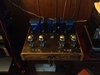
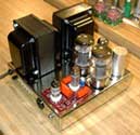
I just completed my SDS board assembly


I also ordered the boards from Shannon and the parts from Mauser today. I forgot to get tube sockets but I may take a look locally and see if there are any.
I also ordered the boards from Shannon and the parts from Mauser today. I forgot to get tube sockets but I may take a look locally and see if there are any.
- Rex Everything
- Posts: 70
- Joined: Sun Feb 22, 2009 6:26 pm
- Location: Las Vegas
![]() by WA4SWJ » Tue Mar 03, 2009 6:33 am
by WA4SWJ » Tue Mar 03, 2009 6:33 am
Rex,
You may have already done this, but trim those leads on the bottom flush with the circuit board. That will improve clearance to ground.
Good luck with your builds. I hope they go very well!
Regards,
You may have already done this, but trim those leads on the bottom flush with the circuit board. That will improve clearance to ground.
Good luck with your builds. I hope they go very well!
Regards,
Ed Long
-
WA4SWJ - KT88
- Posts: 650
- Joined: Mon Dec 27, 2004 8:39 pm
- Location: Belleview, FL
![]() by Ty_Bower » Tue Mar 03, 2009 8:15 am
by Ty_Bower » Tue Mar 03, 2009 8:15 am
Rex Everything wrote:I forgot to get tube sockets but I may take a look locally and see if there are any.
When I was rebuilding my Mk3, it was suggested that I used the 77-MIP-8 sockets. They're outrageously expensive, but they fit the Mk3 chassis perfectly and look completely original. They're supposedly a high quality socket.
The holes in the Mk3 chassis are a bit on the small side, and sockets designed for a 1 3/16" (28mm) hole will not fit, unless you want to bore out the hole.
"It's a different experience; the noise occlusion, crisp, clear sound, and defined powerful bass. Strong bass does not corrupt the higher frequencies, giving a very different overall feel of the sound, one that is, in my opinion, quite unique."
-
Ty_Bower - KT88
- Posts: 1494
- Joined: Wed Mar 21, 2007 2:50 pm
- Location: Newark, DE
![]() by Rex Everything » Tue Mar 03, 2009 12:24 pm
by Rex Everything » Tue Mar 03, 2009 12:24 pm
Ty_Bower wrote:Rex Everything wrote:I forgot to get tube sockets but I may take a look locally and see if there are any.
When I was rebuilding my Mk3, it was suggested that I used the 77-MIP-8 sockets. They're outrageously expensive, but they fit the Mk3 chassis perfectly and look completely original. They're supposedly a high quality socket.
The holes in the Mk3 chassis are a bit on the small side, and sockets designed for a 1 3/16" (28mm) hole will not fit, unless you want to bore out the hole.
Ty,
I am using the Posiedon board and need the 9 pin sockets for it. I'm just gonna use the original power tube sockets for now.
- Rex Everything
- Posts: 70
- Joined: Sun Feb 22, 2009 6:26 pm
- Location: Las Vegas
21 posts
• Page 1 of 2 • 1, 2
Who is online
Users browsing this forum: Google [Bot] and 17 guests