Page 2 of 3

Posted:
Thu Nov 06, 2008 1:07 pmby Ty_Bower
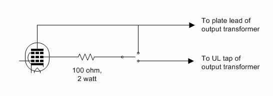
I don't think a four pole switch is required to go between triode and ultralinear. I'd try something like this:


Posted:
Thu Nov 06, 2008 1:43 pmby Blair
This is a PP amp though. Do I not need to do this to both tubes on each channel?
Blair

Posted:
Thu Nov 06, 2008 3:10 pmby Ty_Bower
deicide67 wrote:This is a PP amp though. Do I not need to do this to both tubes on each channel?
Oops. Yellow_Light_Colorz_PDT_14
In that case, I suppose you would need a four pole switch.

Posted:
Thu Nov 06, 2008 3:18 pmby Blair
Well,
Thats good news and bad news. Good because I had it right, and bad because I was exited it may not take as much wiring Yellow_Light_Colorz_PDT_08
Thanks for the follow up Ty!
Should have sockets today or tomorrow, so I really need to get this installed. Like I need another amp!
Blair
I've done this one...

Posted:
Fri Nov 07, 2008 9:41 amby EWBrown
Best approach is a DPDT switch for each channel, and make sure that the switch can handle the relatively DC voltages. And locate it where the casual / curious onlooker can't see or access it. Yellow_Light_Colorz_PDT_11
And, needless to say, don't flip the switch(es) when the amp is running. :o
/ed B

Posted:
Fri Nov 07, 2008 9:47 amby Blair
Ed,
I know this is elementary to you guys, but I do not see how a DPDT switch with work on a PP amp? Are you just running an extra wire to the plate? This switch method will allow me to not have to use any wire. Maybe I'm missing something here..... Yellow_Light_Colorz_PDT_14
Thanks,
Blair

Posted:
Fri Nov 07, 2008 9:54 amby EWBrown
A DPDT switch will work with a PP amp, each "pole" would select the screen grid's connection to either plate or the UL tap on the OPT, for each of the two tubes. Just "mirror" your circuit in the image to show the other side of the PP amp.
Try to locate the switch near to the tube sockets so that the wiring from switch to sockets can be as short as safely possible.
As I mentioned, keeping it out of the view of curious onlookers, it would be best to locate it on the rear panel, or even under the chassis, for the most safety.
/ed B

Posted:
Fri Nov 07, 2008 10:16 amby Blair
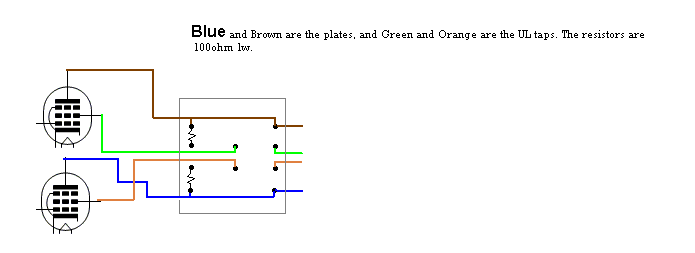
Are referencing Ty's drawing or the one I put on the previous page. I figured if I could get away with everything being on one switch.
This is what I was proposing. I just thought if it was correct, it would make a nice clean looking switch without adding additional wires to the amp.
.gif)
Will this work?
Thanks again Ed!

Posted:
Fri Nov 07, 2008 10:48 amby Ty_Bower
What you've drawn will technically work, but I have a few small complaints:
1) You're wasting a four pole switch (per channel) when a two pole will do. Essentially, the upper and lower poles are just acting as terminal strips. In one throw, they connect the plate to the transformer. In the other throw, they do the same thing. They aren't actually switching anything.
2) As you've drawn it, you want to be absolutely certain no one is ever going to inadvertently throw the switch while the amp is running. There's more than a few henries inductance in the output transformer's primary winding, and you've got over 500 volts potential to start. Opening that switch is going to cut the tube current from 70 mA to zero instantly. I'd expect to see at least a couple kV across the switch contacts for that instant. Not good, and a recipe for a short-lived switch (at best). Of course, it probably isn't good to be switching the UL tap hot either.
I think there was something else, but I've lost it now... Anyway, if you've already got the switches and really want to use them, maybe consider rearrange the plate leads a little bit. Otherwise, just use a two pole switch and mount a small terminal block nearby, land the plate lead to that, and use it for attaching the resistor.


Posted:
Fri Nov 07, 2008 11:03 amby Blair
Good call Ty,
I have two pole switches already, but did not think about the terminal strip. That sounds like the best solution.
Thanks,
Blair

Posted:
Fri Nov 07, 2008 9:42 pmby Ty_Bower
Looking at what I've drawn, I'd take it a step further and wire it up so the resistor is always in the circuit in series with the screen. I believe that's a worthwhile addition, especially considering you're using solid state rectification.

Posted:
Sat Nov 08, 2008 8:23 amby Blair
So, you are saying to wire it downstream towards the tube socket? Like a grid stopper would be?
I may still use the 4 pole switch for space reasons and because I alsready have bot types of switches. It is one less strip under there. I looked at it last night and adding another terminal strip is not as easy as it sounds without drilling a few more holes in the top plate. Is there safety issues with using the four pole switch the way You drew it. Noone touches my gear while it is on or off for that matter. Just me.
Thanks,
Blair

Posted:
Sat Nov 08, 2008 7:31 pmby EWBrown
The 100 ohm 1W resistor should connect directly to the screen grid contact on the socket, that way it is always in, for both UL or triode modes. Think of it as being a grid stopper resistor. then the other end of the resistors can go to the center contacts of the DPDT switch, one for each tube.
The extra two poles on a 4PDT switch could be used as terminal strips, if needed. Just don't use the center contacts on those two "extra" poles.
/ed B

Posted:
Sat Nov 08, 2008 10:50 pmby Blair
Thanks Ed! I'll get it finished soon. I'm still waiting on sockets.
Blair

Posted:
Mon Nov 10, 2008 7:41 amby EWBrown
FWIW, both VTL (Vacuum Tube Logic) and Manley use this same mode-switching process on many of their PP amps, from the 45/25 watt "tiny triode" monoblocks, to their massive 600 and 1200 watt monsters.
They heartily recommend that the mode switches NOT be flipped while the am is poqwered up.
/ed B


.gif)
