by erichayes » Tue Jan 22, 2008 2:07 am
I think I've touched on this in previous threads, but . . .
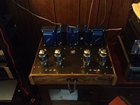
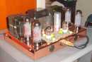
"Screen grid stopper" is a misnomer. The screen grid is either working in phase with the plate of an output tube (UL or Williamson operation), or it's an independently powered accelerator having no signal imposed on it (pentode operation).
A control grid stopper, on the other hand, is intended to eliminate parasitic oscillation, and is usually valued between 1K and 10KΩ. ½ watt carbon comp is the construction of choice (although I want to challenge that sometime in the future), and the resistor needs to be located as close to the control grid as possible.
The screen grid resistor would be more accurately called a ballast resistor, in that its intention is to equalize G2 current between tubes. It also lowers the potential on the screens to be below the plate voltage in UL operation. Anyone who's witnessed brightly glowing screens can appreciate this addition. The usual value for a ballast resistor is between 33 and 220Ω, but YMMV.
Eric in the Jefferson State